
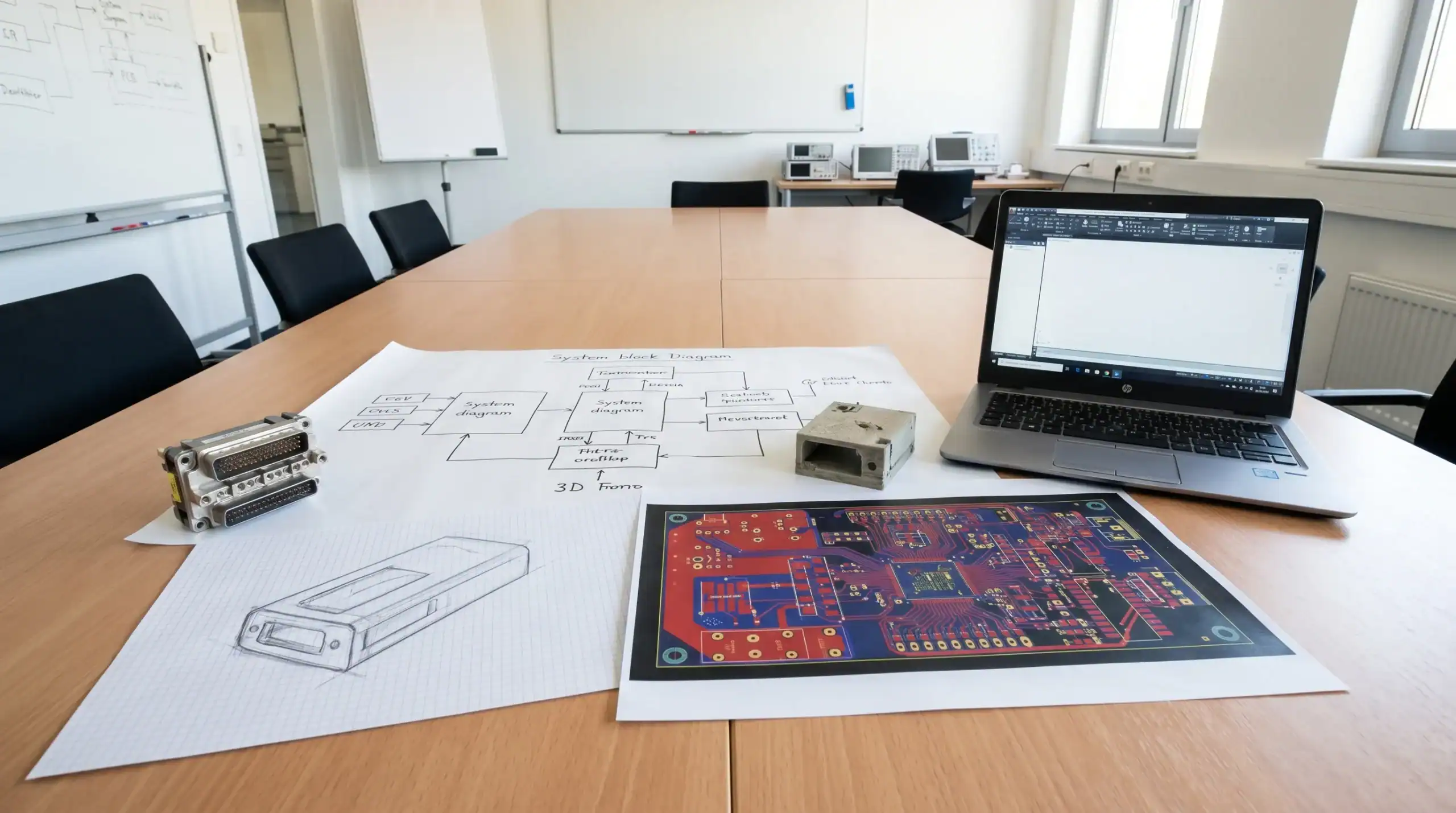
For many OEMs, custom electronics design starts too late. Not because the project team waits too long to contact an electronics partner, but because the first conversations focus on circuits, components or PCB dimensions before the product problem is fully defined.
A schematic can only be as good as the assumptions behind it. If the operating environment, safety constraints, user behaviour, interfaces, power profile and production expectations are unclear, the design team is forced to make decisions that may later become expensive to reverse. The prototype may work on the bench, yet fail during EMC testing, field trials or production scaling.
Before starting custom electronics design, OEMs should not aim to write a perfect specification. That is rarely realistic. They should, however, define the critical context well enough for engineers to make robust system-level decisions. This early definition phase reduces technical risk, improves collaboration and helps turn a product idea into electronics that are reliable, manufacturable and maintainable.
Why definition matters before the first schematic
Electronic product development is a chain of dependent decisions. A connector choice can influence enclosure sealing. A wireless module can affect the antenna layout, enclosure material, RED compliance route and power budget. A motor drive topology can affect thermal design, EMC behaviour, PCB stack-up and safety margins.
When OEMs only define the visible function, they leave hidden requirements unresolved. These hidden requirements often appear later as disturbances, overheating, certification delays, firmware edge cases, unavailable components or assembly problems.
Good early definition does three things. It aligns the commercial goal with the technical architecture. It makes trade-offs visible before design effort is committed. It gives the electronics design partner enough context to challenge assumptions and propose safer, more scalable options.
This is especially important for professional markets such as machine manufacturing, robotics, maritime, defence, automotive, high-tech equipment and industrial IoT. In these environments, electronics must perform consistently under vibration, electrical noise, temperature variation, long service life expectations and strict compliance requirements.
Define the product objective and success criteria
The first question is not what electronics should be built. It is what the product must achieve in the market and in the hands of its users.
An OEM should be able to explain the product purpose, the problem it solves, the intended users and the conditions in which success will be measured. This includes performance targets, reliability expectations, installation context, maintenance approach and commercial constraints such as target production volumes.
For example, a sensor platform for a machine builder may need to measure accurately despite nearby motor drives and switching power supplies. A connected maritime device may need to survive humidity, salt exposure and unreliable power input. A consumer wellness product may have a very different set of user interaction and data requirements. In health-related applications, the functional context may even be shaped by domain experts and service models such as personalised nutrition consultations, where the device must support meaningful data capture rather than merely collect signals.
This context helps engineers decide whether the product needs a simple embedded controller, a more powerful embedded computing platform, custom analogue front-end circuitry, galvanic isolation, wireless connectivity, local diagnostics or a different system architecture altogether.
A useful starting point is to define success in measurable terms. Examples include response time, measurement accuracy, power consumption, operating temperature range, expected service life, maximum enclosure size, supported interfaces, maintenance interval and acceptable failure behaviour.
Define the real operating environment
Many electronics issues are not caused by bad design in isolation. They are caused by design decisions that were reasonable for the lab but unsuitable for the real environment.
OEMs should define the operating envelope before development begins. That means describing not only normal use, but also credible extremes and misuse scenarios. Engineers need to understand where the product will be installed, what it will be connected to, who will handle it, how it will be powered and what disturbances may be present.
Important environmental factors include temperature, humidity, dust, water exposure, vibration, shock, UV exposure, chemical exposure and mechanical stress. Electrical factors include supply voltage variation, transients, reverse polarity risk, electrostatic discharge, nearby switching loads, cable lengths and grounding conditions.
The more demanding the environment, the more important it becomes to treat electronics, enclosure design and cabling as one system. A PCB layout cannot fully compensate for an enclosure that creates thermal bottlenecks or cable routing that introduces EMC problems.
If the product will be used outside controlled laboratory conditions, early field context is essential. ProMicro has discussed this in more detail in its article on why embedded electronics fail outside the lab and how to prevent it.
Define system boundaries and interfaces
A custom electronics design rarely operates alone. It may connect to motors, sensors, batteries, displays, cloud services, industrial networks, actuators, safety circuits, existing machinery or third-party software.
OEMs should define what is inside the design scope and what remains outside it. This avoids ambiguity between hardware, embedded software, mechanical design, manufacturing and system integration responsibilities.
Interfaces should be documented as early as possible. Even a preliminary interface overview can prevent major misunderstandings. Useful details include connector types, signal levels, communication protocols, cable lengths, update mechanisms, diagnostic access and mechanical mounting constraints.
For embedded systems, hardware and software boundaries are particularly important. A function can often be implemented in hardware, firmware or a combination of both. The best choice depends on timing, safety, cost, updateability, power consumption and reliability.
This is where system engineering adds value. Instead of treating PCB design as an isolated task, system engineering considers the full product architecture and the interactions between electronics, software, mechanics, compliance and manufacturing.
Define power, analogue and performance requirements
Power electronics and analogue electronics are often underestimated at the start of product development. Digital functions are easier to describe, while power quality, signal integrity and transient behaviour remain hidden until testing reveals problems.
Before starting custom electronics design, OEMs should define how the product is powered and what loads it must control or measure. This includes supply voltage range, peak current, inrush current, battery operation, charging requirements, motor behaviour, thermal dissipation and required protection functions.
For analogue electronics, the team should define signal types, expected ranges, noise sensitivity, sensor accuracy, sampling requirements and calibration needs. If the product measures small signals in a noisy industrial environment, the analogue front end, PCB layout, grounding strategy and filtering approach become critical design decisions.
Power and analogue requirements also influence enclosure design. Heat must leave the product somehow. Sensitive signals must be protected from interference. Cables and connectors must be chosen for both electrical and mechanical reliability.
The table below summarises several areas OEMs should clarify before development starts.
| Area to define | Why it matters | Examples of useful detail |
|---|---|---|
| Product function | Guides architecture and trade-offs | Measurement, control, communication, safety behaviour |
| Operating envelope | Prevents lab-only design assumptions | Temperature, vibration, humidity, power disturbances |
| Interfaces | Reduces integration risk | Sensors, motors, CAN, Ethernet, USB, wireless, cloud |
| Power profile | Shapes topology, protection and thermal design | Input range, peak load, standby current, battery needs |
| Analogue performance | Protects measurement quality | Accuracy, resolution, noise limits, calibration approach |
| Mechanical constraints | Aligns PCB, enclosure and assembly | Size, mounting, sealing, cable routing, heat transfer |
| Compliance context | Avoids late redesigns | EMC, RED, CE, safety, sector-specific standards |
| Production assumptions | Supports manufacturability | Volumes, test strategy, supply chain, service life |
Define the compliance route early
Compliance should not be treated as an activity at the end of the project. It should influence architecture, component selection, PCB layout, enclosure design, cabling and firmware behaviour from the start.
For products sold in Europe, the relevant compliance route may involve CE marking, EMC requirements, the Radio Equipment Directive for wireless products, the Low Voltage Directive, RoHS, safety standards or sector-specific rules. The European Commission's CE marking guidance is a useful starting point for understanding the general framework, although each product still needs its own assessment.
OEMs do not need to know every test detail before engaging a design partner. They should, however, define the intended market, product category, wireless technologies, voltage levels, safety relevance and installation environment. These factors determine which standards may apply and how the product should be designed.
Designing with compliance in mind does not guarantee a first-pass certification result. No responsible engineering partner should promise that without testing. It does, however, reduce avoidable risks. Early EMC thinking, for example, can influence PCB stack-up, grounding, filtering, shielding, connector placement and enclosure decisions. ProMicro has covered this topic separately in its explanation of what EMC is and why it matters.
Define mechanical and enclosure constraints
Electronics and mechanics are often developed in parallel, but they cannot be treated as separate worlds. Enclosure decisions affect thermal performance, EMC behaviour, antenna performance, assembly time, connector accessibility and serviceability.
Before custom electronics design begins, OEMs should define the expected product form factor, mounting method, ingress protection needs, user access points, cable entry locations and any aesthetic or ergonomic constraints. If the product will be handheld, installed in a cabinet, mounted on a vehicle or integrated into a machine, that context changes the electronics design.
Thermal management is one of the most common reasons for late-stage redesign. A compact enclosure may look attractive but create heat concentration around power components. A metal enclosure may help shielding but affect antenna performance. A plastic enclosure may simplify wireless communication but require different EMC measures.
The aim is not to finalise every mechanical detail at the start. The aim is to make sure the electrical and mechanical concepts evolve together.
Define software, connectivity and data expectations
Modern custom electronics often include embedded software, connectivity and data processing. OEMs should define what the device must do locally, what it may send externally and how it should behave when communication fails.
This includes firmware update strategy, security expectations, diagnostic functions, logging, user interaction, cloud or gateway integration and communication protocols. For IoT device design, the decision between local processing, edge intelligence and cloud dependency can have major consequences for latency, power consumption, cybersecurity, data cost and product reliability.
Connectivity also affects compliance. A product using wireless communication may need a different design and test approach than a wired product. Antenna placement, enclosure material, coexistence with other electronics and firmware radio behaviour all matter.
For OEMs, the key is to define the role of software in the product. Is firmware simply controlling hardware, or is it part of the product's core value? Does the product need field updates? Should it include diagnostics for service teams? Will data be used for predictive maintenance, traceability or regulatory documentation?
These decisions should be visible before architecture is fixed.
Define manufacturing, test and lifecycle assumptions
A prototype is not the same as a production-ready product. If OEMs intend to move towards volume manufacturing, they should define production assumptions before the first PCB is laid out.
This includes expected annual volumes, cost targets, assembly method, test coverage, programming process, calibration needs, traceability requirements and service strategy. Even approximate ranges are useful. A design for ten prototypes may look different from a design for thousands of units per year.
Manufacturing readiness also depends on component availability. Long lifecycle products need careful component selection, second-source thinking and documentation that supports future maintenance. A technically excellent design can still create business risk if it depends on parts with uncertain availability or poor supply chain resilience.
Test strategy deserves early attention. If a product cannot be tested efficiently during production, quality issues may become expensive and difficult to diagnose. Design for test can include test pads, built-in self-test functions, firmware diagnostics, programming access and clear acceptance criteria.
ProMicro explores this transition in more depth in its guide on preparing a PCB design for prototyping and volume build.
What does not need to be fully defined?
OEMs sometimes delay engagement because they believe they need a complete specification first. In practice, involving an electronics design partner earlier can be more effective, especially when requirements are complex or incomplete.
The following items can often remain flexible at the start:
- Exact PCB dimensions, if the enclosure concept is still evolving.
- Final component selection, if performance and lifecycle requirements are known.
- Detailed firmware implementation, if system behaviour and interfaces are clear.
- Final production test fixtures, if testability is considered in the architecture.
- Complete compliance documentation, if the intended markets and product category are known.
The important distinction is between open decisions and hidden assumptions. Open decisions can be managed. Hidden assumptions usually become project risk.
A practical pre-development checklist for OEMs
Before starting custom electronics design, OEMs should aim to prepare a concise but structured input package. It does not need to be perfect, but it should make the product context clear.
Useful artefacts include:
- A product requirements document with must-have and nice-to-have functions.
- A system block diagram showing electronics, software, mechanics and external interfaces.
- An operating envelope covering environmental, electrical and mechanical conditions.
- A preliminary compliance overview for intended markets and technologies.
- A power and signal overview for supplies, loads, sensors and communication.
- A mechanical concept with size, mounting, enclosure and cable constraints.
- A prototype plan explaining what should be proven and how success will be measured.
- A production assumption covering volumes, test needs, service life and lifecycle risks.
This level of preparation allows a design partner to ask better questions. It also helps the OEM compare architecture options based on risk, reliability, cost, compliance and scalability rather than only on development effort.
How ProMicro supports early definition and custom electronics design
ProMicro supports OEMs from early idea generation through embedded system development, power electronics, analogue electronics, PCB design, enclosure considerations, prototyping and preparation for volume manufacturing.
The value of an integrated development partner is not only execution capacity. It is the ability to identify hidden technical risks before they become locked into the design. That includes risks around EMC, power integrity, thermal behaviour, component lifecycle, firmware-hardware interaction, manufacturability and real-world use.
For OEMs with internal engineering teams, this can provide specialist capacity where it is needed most. For companies without a full electronics department, it creates a structured path from concept to production-ready electronics. In both cases, the strongest results come when requirements, architecture and validation are discussed before the schematic is treated as the starting point.
Custom electronics design is most effective when it begins with the full system in view. The PCB is important, but it is only one part of a product that must function safely, reliably and economically throughout its lifecycle.
Frequently asked questions
How detailed should requirements be before contacting an electronics design partner? Requirements do not need to be complete, but the product goal, operating context, key functions, interfaces, intended market and main constraints should be clear enough to support technical discussion. A good partner can help refine incomplete requirements.
Should OEMs define the PCB before the system architecture? Usually not. PCB decisions should follow system-level choices about power, signals, firmware, mechanics, compliance and manufacturing. Starting with the PCB too early can lock in assumptions that later create reliability or certification problems.
When should EMC and compliance be considered? EMC and compliance should be considered at the beginning of development. Early decisions about layout, grounding, filtering, enclosure, cables and wireless technology can strongly influence the likelihood of a smoother compliance process later.
Can custom electronics design still be flexible if requirements change? Yes, but flexibility depends on architecture. Modular design, clear interfaces, documented assumptions and staged validation make it easier to manage changes without uncontrolled redesign.
What is the biggest risk when OEMs start development too quickly? The biggest risk is building a prototype that proves the obvious function but ignores hidden requirements such as thermal behaviour, EMC, manufacturability, component availability or field reliability. These issues are usually more expensive to solve later.
Planning a custom electronics project?
If your organisation is preparing a new product, machine module, connected device or embedded control system, define the critical context before committing to detailed design. The earlier hidden requirements are made visible, the easier it becomes to reduce risk and build electronics that are ready for real-world use.
ProMicro helps OEMs turn complex product ideas into reliable embedded systems, power electronics, analogue electronics and production-ready designs. To discuss your development challenge, visit ProMicro and start the conversation with a team that understands both the engineering details and the full product lifecycle.
