
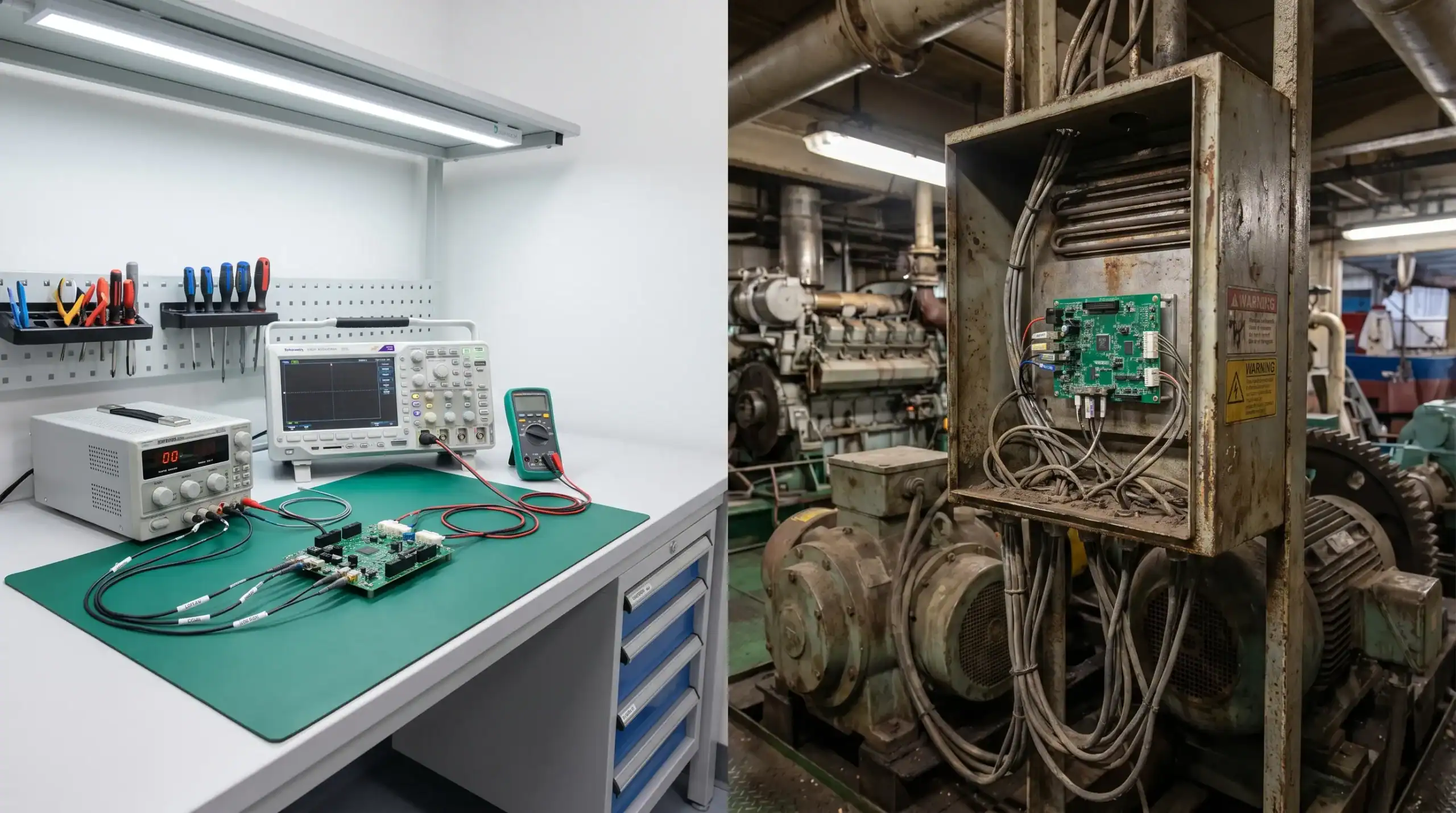
A prototype that behaves perfectly on the bench can still become unreliable once it is installed in a machine, vehicle, vessel or connected product. That is not because lab testing has no value. It is because the lab is usually cleaner, cooler, more predictable and more controlled than the environment the product will actually face.
For technical directors, CTOs and engineering managers, this is one of the most expensive gaps in product development. The design appears to work, the first demonstration is convincing, but later the system suffers from resets, interference, overheating, unexplained sensor errors, unstable communication or certification delays.
In embedded electronics, field failure is rarely caused by one dramatic mistake. More often, it is the result of assumptions that were never translated into requirements: the real input voltage range, cable length, enclosure temperature, user behaviour, vibration profile, EMC environment, maintenance process or production variation.
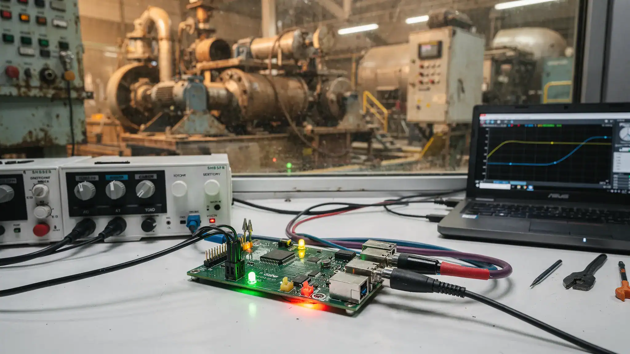
Why lab success does not guarantee field reliability
A lab prototype proves that a concept can work under a limited set of conditions. A production-ready embedded product must work across a much wider operating envelope, often for years, with variation in components, users, installations and environmental stress.
In the lab, engineers often use stable power supplies, short cables, accessible test points, controlled ambient temperature and known test sequences. In real use, the same electronics may be connected to a noisy DC bus, placed inside a sealed enclosure, exposed to salt air, installed next to motor drives, handled by non-technical users or operated during voltage dips and temperature extremes.
This difference matters especially in professional markets such as machine manufacturing, robotics, maritime, automotive, defence, high-tech equipment and connected industrial products. In these applications, embedded electronics are part of a larger system. The PCB, firmware, sensors, power stage, connectors, enclosure, cables, communication interfaces and mechanical installation all influence reliability.
A robust design process therefore needs to answer more than one question. It is not enough to ask: does the circuit work? The better question is: does the complete system work safely, repeatably and manufacturably in its intended environment?
Common reasons embedded electronics fail outside the lab
Power input conditions are underestimated
Many embedded systems are validated with a clean bench supply. Real installations are rarely that clean. Industrial machines, battery-powered platforms, vehicles, vessels and robotic systems can create voltage dips, surges, reverse polarity risks, ground offsets, inrush currents, load switching effects and conducted noise.
A microcontroller reset during a voltage dip may look like a firmware bug. A sensor reading that drifts under motor load may look like an analogue design issue. A communication fault during startup may be caused by power sequencing. Without realistic power testing, these issues are often discovered late.
Preventive measures include input protection, filtering, transient suppression, suitable grounding strategy, defined startup and shutdown behaviour, brownout handling, power rail monitoring and adequate derating. For power-heavy products, the power stage should be designed for the actual load profile, switching behaviour, thermal path and EMC environment, not only for the headline datasheet values.
This is why custom power electronics often become necessary when off-the-shelf modules do not match the real application. ProMicro has discussed this in more detail in its article on custom power electronic solutions.
Thermal conditions change once the product is enclosed
A board that runs cool on an open bench can overheat inside an enclosure. The difference can be significant when the product is sealed for ingress protection, mounted near motors or power components, exposed to sunlight, installed in a cabinet or operated at high duty cycle.
Thermal failure is not always immediate. Components may stay within absolute maximum ratings during a short test, yet suffer reduced lifetime due to continuous operation at elevated temperature. Capacitors, power semiconductors, inductors, voltage regulators and connectors are particularly sensitive to thermal stress.
Good thermal design starts early. It includes realistic ambient temperature assumptions, power loss estimation, component derating, PCB copper strategy, thermal vias, airflow constraints, heat spreading, enclosure material choices and mounting conditions. Thermal testing should measure component temperatures in representative operating modes, not only the air temperature around the board.
EMC and interference are treated as a final test
Electromagnetic compatibility is one of the most common reasons electronics behave differently outside the lab. Long cables can act as antennas. Switching power supplies can inject noise. Motor drives, radio modules and high-speed digital interfaces can disturb analogue measurements. ESD from users can cause latch-up or resets. Nearby transmitters can affect communication or sensing performance.
If EMC is addressed only after the product is functionally complete, redesign can become expensive. PCB layout, grounding, filtering, shielding, connector placement, cable routing and enclosure design all influence emissions and immunity. These choices are difficult to correct at the end without changing the architecture.
Designing with EMC in mind does not guarantee a pass at formal testing, but it reduces avoidable risk. Pre-compliance measurements, conducted immunity checks, ESD testing, radiated emission scans and careful review of current return paths can reveal problems before certification becomes a bottleneck. For a deeper explanation, read ProMicro’s guide on what EMC means in electronic product design.
Mechanical stress affects electrical performance
Embedded electronics are physical products. Vibration, shock, connector movement, cable strain, condensation, dust, salt mist and repeated handling can all cause electrical issues. A connector that is reliable on the bench may loosen in a vibrating machine. A cable shield that works in one installation may be terminated incorrectly in another. A sensor board may be affected by mechanical stress, causing measurement drift.
In maritime, defence, automotive and industrial applications, mechanical integration is not separate from electronics design. The enclosure, PCB fixation, connector selection, sealing approach, cable routing and service access must be considered together. Design reviews should include mechanical and electrical stakeholders, because reliability often depends on the interface between the two.
Firmware is not designed for abnormal states
Many prototypes are tested through expected workflows: power on, connect, measure, communicate, shut down. Field use introduces edge cases. Users disconnect cables at the wrong time. Wireless signals drop. Sensors return invalid data. Batteries sag. Memory becomes full. A peripheral does not respond after startup. A bootloader update is interrupted.
When firmware is not designed for these states, the hardware may appear unreliable even when the electronics are sound. Robust embedded software should include watchdog strategy, fault detection, safe states, retry logic, timeout handling, error logging, diagnostics and clear recovery behaviour. For connected devices, communication loss and reconnection must be treated as normal operating conditions, not exceptional events.
The important point is that firmware and hardware reliability cannot be separated. Brownout thresholds, reset circuits, power sequencing, sensor interfaces and software state machines must be designed as one system.
Requirements do not reflect real users and service conditions
Some failures happen because the product was designed for the stated requirement, not for the real situation. A specification may say indoor use, while the product is installed near an open loading door. It may define a cable length of two metres, while the field installation uses eight metres. It may assume trained operators, while the product is used by temporary staff. It may specify a nominal input voltage, while the actual supply varies widely during startup.
These hidden requirements are often discovered through structured discussions with sales, service, installation teams, end users and manufacturing partners. Scenario-based thinking helps teams uncover what can go wrong before the product is built. Some organisations strengthen this capability by training commercial and service teams with tools such as AI roleplay simulations for realistic customer and field scenarios, so that early conversations capture better objections, use cases and operational details before they reach engineering.
For embedded product development, this matters because every missing requirement can become a late design change.
Prototype shortcuts become production problems
A prototype often contains acceptable shortcuts: hand modifications, oversized components, development modules, temporary wiring, manual calibration or limited test coverage. These choices are useful for learning, but they should not silently become part of the production design.
When moving towards volume manufacturing, the design must support repeatable assembly, inspection, programming, testing, calibration, repair and component sourcing. Test points, programming access, production tolerances, panelisation, connector access and end-of-line test strategy should be considered before the PCB is frozen.
A product that works once is not the same as a product that can be built reliably 100, 1,000 or 10,000 times.
Failure modes and prevention measures
The table below summarises typical gaps between lab validation and field reliability.
| Field failure risk | Typical lab assumption | Prevention approach |
|---|---|---|
| Unexpected resets | Stable bench power supply | Test dips, surges, startup sequencing, brownout behaviour and load switching |
| Overheating | Open-board testing at room temperature | Validate thermal performance inside the real enclosure and duty cycle |
| EMC issues | Short cables and quiet lab environment | Design PCB layout, grounding, filtering, shielding and cable strategy early |
| Sensor drift or noise | Clean signals during bench tests | Test with real cable lengths, nearby power electronics and representative grounding |
| Communication instability | Strong wired or wireless connection | Include timeout handling, retries, diagnostics and reconnection behaviour |
| Connector or solder failures | Static bench setup | Test vibration, strain relief, fixation and installation handling |
| Production variation | One carefully assembled prototype | Apply design for manufacturing, test coverage and component lifecycle planning |
How to prevent field failures before they become expensive
Start with the operating envelope, not the schematic
The schematic is not the starting point of a reliable product. The starting point is the operating envelope: where the product is installed, who uses it, how it is powered, what it connects to, what disturbances it faces, how it is serviced and how long it must remain available.
For a professional embedded product, requirements should cover electrical, mechanical, environmental, software, compliance, manufacturing and lifecycle aspects. This does not mean every requirement must be perfect on day one. It means assumptions must be made visible, reviewed and tested as the design matures.
Useful early questions include:
- What are the true minimum and maximum supply conditions?
- Which cables leave the enclosure, and how long can they be?
- What heat sources exist inside and outside the product?
- Which standards or directives may influence EMC, RED, CE or safety design?
- What happens when communication, sensors or power fail temporarily?
- How will the product be programmed, tested, calibrated and serviced in production?
These questions reduce the risk of designing a beautiful PCB that solves only part of the problem.
Design the system architecture around risk
Architecture decisions determine how easily a product can be made robust. Partitioning analogue and digital domains, separating noisy power stages from sensitive measurement circuits, choosing suitable isolation, defining communication boundaries and selecting connectors all influence reliability.
For example, a robotic system with motor drives, sensors and wireless communication needs more than a controller board. It needs a system architecture that manages high current paths, signal integrity, EMC, thermal load, safety behaviour and firmware timing. A maritime monitoring product may need special attention to corrosion, condensation, grounding and long cable runs. A connected consumer or professional product may need careful coexistence between wireless communication, power conversion and enclosure constraints.
Early architecture reviews are valuable because they identify risks while changes are still affordable.
Build prototypes to answer specific technical questions
A prototype should not only demonstrate functionality. It should answer risk questions. If the highest risk is thermal behaviour, the prototype must represent the enclosure and power losses. If the highest risk is EMC, the prototype must include realistic cables, grounding and switching circuits. If the highest risk is production scaling, the prototype should include manufacturing test access and realistic component choices.
Different prototypes can serve different purposes. A proof-of-concept validates feasibility. An engineering prototype validates architecture and critical functions. A pre-production prototype validates manufacturability, compliance readiness and repeatability. Confusing these stages creates false confidence.
Test progressively under realistic conditions
Waiting for final qualification testing is risky. A better approach is progressive validation throughout development. This can include bench measurements, fault injection, environmental screening, pre-compliance EMC work, firmware robustness testing and production test development.
The exact test plan depends on the industry and application, but the principle is consistent: test the most important assumptions early enough to change the design.
Relevant test areas often include:
- Electrical robustness, including input range, transients, reverse polarity, inrush and power sequencing
- Thermal behaviour, including high ambient temperature, enclosure effects and continuous operation
- EMC behaviour, including emissions, ESD, conducted immunity and radiated immunity where relevant
- Mechanical robustness, including vibration, shock, connector strain and installation handling
- Firmware resilience, including watchdogs, invalid sensor data, communication loss and recovery behaviour
- Manufacturing readiness, including programming, test points, calibration, inspection and traceability
This approach does not remove the need for formal testing where required, but it makes formal testing less of a blind leap.
Treat PCB layout as a system-level design activity
PCB layout is sometimes underestimated as an implementation task. In embedded electronics, layout can determine whether the product is quiet, stable, manufacturable and thermally reliable.
Return currents, loop areas, impedance, creepage and clearance, component placement, decoupling, grounding, isolation and thermal copper all matter. So do connector positions, test access, enclosure fit and assembly constraints. A technically correct schematic can still fail because of poor layout choices.
This is especially important when embedded systems combine power electronics, analogue measurement, wireless communication and dense digital processing on the same board or within the same enclosure.
Plan for lifecycle and component availability
A field product is not finished when the first production batch ships. Components may become obsolete, suppliers may change specifications, firmware may need updates and customers may request variants. If lifecycle planning is ignored, a reliable product can become difficult to maintain.
Long-term thinking includes component selection, second-source options where possible, documentation quality, firmware maintainability, modular architecture and clear production data. For companies developing product families or platforms, this can reduce future redesign effort and improve scalability. ProMicro’s article on scalable embedded system development explains this platform-oriented mindset in more depth.
What decision-makers should look for in an electronics development partner
Preventing field failures requires more than extra engineering hours. It requires a partner who can connect disciplines and challenge assumptions early. For CTOs, technical directors and product owners, the right partner should be able to discuss the complete system, not only a PCB task.
Look for expertise in embedded systems, power electronics, analogue electronics, PCB design, system engineering, enclosure integration, prototyping and manufacturing preparation. Just as importantly, look for a partner who asks questions about real-world use, compliance constraints, lifecycle expectations and hidden technical risks.
This collaboration model is particularly valuable when internal teams have strong product knowledge but limited capacity or specialist electronics expertise. The internal team keeps ownership of the product vision, while the external partner helps translate that vision into robust, testable and production-ready electronics.
How ProMicro supports robust embedded electronics development
ProMicro supports companies from early idea generation through prototyping and towards volume solutions. The focus is not only on making electronics functional, but on making them reliable, scalable and suitable for real operating conditions.
This includes embedded system development, power electronics expertise, analogue electronics design, PCB design services, system engineering, enclosure design, rapid prototyping, manufacturing preparation and lifecycle thinking. For complex products, these disciplines need to be considered together. A sensor interface can be affected by power design. EMC can be affected by enclosure and cabling. Firmware behaviour can depend on power sequencing. Manufacturing readiness can depend on layout decisions made months earlier.
By addressing explicit requirements and hidden risks early, ProMicro helps reduce the chance that a prototype works in the lab but fails during certification, production scaling or field use.
Frequently asked questions
Why do embedded electronics work in the lab but fail in the field? Lab conditions are controlled. Field conditions introduce power disturbances, temperature variation, EMC exposure, vibration, cable effects, user behaviour and production variation. If these factors are not included in requirements and testing, the prototype can give false confidence.
When should EMC be considered in embedded electronics design? EMC should be considered from the architecture and PCB layout stage. Grounding, filtering, cable routing, shielding, enclosure design and component placement are much easier to optimise early than after a failed compliance test.
What is the difference between a prototype and production-ready electronics? A prototype proves technical feasibility. Production-ready electronics must also be manufacturable, testable, compliant-minded, thermally robust, maintainable and reliable across component and operating variation.
How can we reduce risk when requirements are not fully clear? Start by documenting assumptions and identifying the highest technical risks. Use workshops, field scenarios, early architecture reviews and targeted prototypes to validate those assumptions before committing to the final design.
Can an external electronics partner work alongside an internal engineering team? Yes. This is often the most effective model. The internal team contributes product knowledge and business priorities, while the external partner adds specialist expertise in embedded systems, power electronics, analogue design, PCB layout, compliance-aware design and manufacturing preparation.
Develop embedded electronics that survive real-world use
If your product needs to move from concept or prototype to reliable field operation, the most important work happens before the design is frozen. Power behaviour, EMC, thermal design, firmware resilience, enclosure integration and manufacturing readiness all need attention early.
ProMicro helps companies develop embedded electronics for demanding professional applications, from first idea to prototype and towards volume manufacturing. If you are developing a complex machine, connected product, robotic system, maritime application, high-tech device or power-focused embedded platform, contact ProMicro to discuss how to reduce technical risk and build a more robust product development path.
