
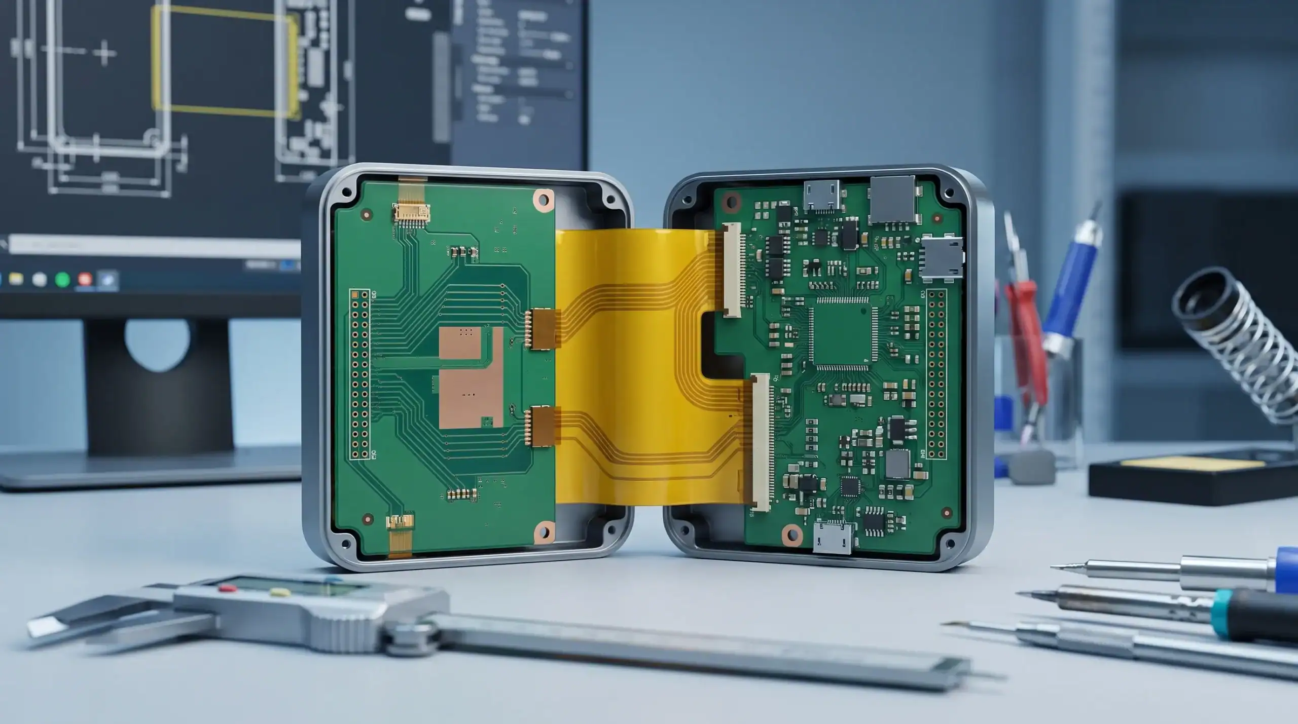
Flexible PCBs can be an excellent product design choice, but only when the mechanical, electrical and manufacturing reasons are strong enough to justify the extra design discipline. In professional electronics, they are rarely just a neat way to save space. They influence system architecture, assembly strategy, EMC behaviour, reliability, thermal performance, testability and long-term serviceability.
For engineering managers, CTOs and product development teams, the real question is not whether flexible PCBs are technically possible. It is whether they reduce risk in the full product lifecycle, from concept and prototype to certification, production and field use.
Why flexible PCBs are a system-level decision
A flexible PCB is not simply a rigid PCB made bendable. It uses different materials, stack-ups, coverlay systems, manufacturing processes and mechanical design rules. That means the decision should be made early, before the enclosure, connector strategy, sensor placement, power architecture and assembly process are locked in.
This is especially important in embedded systems, robotics, high-tech equipment, automotive products, maritime electronics and defence-related applications, where products often face vibration, temperature variation, moisture, restricted space and long service expectations. In these environments, a flexible circuit can either solve a genuine integration problem or become a hidden reliability risk.
The same principle applies to any PCB architecture: reliability and EMC are designed in from the beginning, not corrected at the end. For a wider view on this point, ProMicro has covered how PCB board design affects reliability and EMC in conventional and complex electronic products.
With flexible PCBs, the electrical design and the mechanical design are inseparable. A bend area is also a stress area. A ground reference may also be a stiffness contributor. A connector replacement may improve assembly repeatability, but make repair less modular. These trade-offs need to be visible before detailed layout begins.
Flexible PCB, rigid-flex PCB or rigid PCB: what is the difference?
A flexible PCB typically consists of copper conductors on a flexible dielectric material, often polyimide, with a coverlay instead of the solder mask used on many rigid PCBs. It can be designed to bend once during assembly or to move repeatedly during operation, but these two use cases require very different engineering assumptions.
A rigid-flex PCB combines rigid PCB sections and flexible interconnect sections into one integrated board structure. Components are usually placed on rigid areas, while the flex sections replace cables, connectors or separate interconnects between those areas. This can be valuable in compact products where assembly reliability and packaging density are critical.
A standard rigid PCB remains the right choice for many products. If the board does not need to bend, does not need to connect moving or folded sections, and has enough enclosure space, a rigid board will often be simpler to design, manufacture, test and service.
| PCB architecture | Best suited for | Typical strengths | Typical risks |
|---|---|---|---|
| Rigid PCB | Stable board placement with no bending requirement | Mature manufacturing, easier assembly, good thermal options, broad supplier base | May require extra connectors, cables or enclosure volume |
| Flexible PCB | Folded, curved or moving interconnects | Space saving, lower weight, fewer harnesses, 3D packaging options | Bend fatigue, material constraints, handling sensitivity, higher design complexity |
| Rigid-flex PCB | Compact multi-board systems with integrated interconnects | Reduced connector count, improved assembly repeatability, strong packaging integration | Higher fabrication cost, more complex stack-up, stricter DFM requirements |
The choice is therefore architectural. It should be evaluated alongside enclosure design, component placement, connector count, test access, environmental exposure and manufacturing strategy.
When flexible PCBs make sense
Flexible PCBs make the most sense when they solve a problem that a rigid PCB or cable harness cannot solve cleanly. In many professional products, the best justification is not aesthetic compactness, but reliability, repeatable assembly or mechanical integration.
The product needs a compact 3D layout
Flexible circuits are useful when electronics must fit into non-rectangular, curved or very compact spaces. Examples include sensor modules, handheld industrial devices, camera systems, display interfaces, control panels and dense embedded modules inside machines.
A flex circuit can fold around an enclosure feature, connect boards placed at different angles or route signals through a hinge-like space without bulky wiring. This can help avoid awkward connector placement or fragile manual wiring during assembly.
However, the enclosure must be designed with the flex in mind. If the mechanical team reserves too little bend space, the flex may be forced into a radius that exceeds its fatigue limits. If screw bosses, sharp housing edges or moving parts touch the flex, field failures can occur even when the electrical design is correct.
The interconnect must move during operation
Robotic joints, moving sensor heads, sliding mechanisms and certain automotive or machine-building applications may require electrical interconnects that move repeatedly. In these cases, a properly designed flexible PCB can be more controlled than a loose cable harness.
The key phrase is properly designed. Dynamic flexing requires attention to bend radius, copper type, layer count, trace orientation, stiffener placement and strain relief. A flex designed only for installation bending should not be assumed suitable for repeated motion.
For dynamic applications, the product team should define expected movement early. That includes bend angle, cycle count, speed, temperature, vibration and any torsion. A flex circuit that bends in one controlled direction may perform very differently from one that twists or rubs against a housing.
Connectors and wire harnesses create too much assembly risk
Every connector, cable and manual wiring step can introduce variation. In low to medium volume professional products, this often appears as assembly time, rework or inconsistent field reliability. In higher volume products, it can affect yield and test complexity.
A flexible PCB or rigid-flex design can reduce the number of connectors and harnesses. That may improve assembly repeatability and reduce the risk of miswiring, loose connections or connector wear. It can also make the product easier to assemble in a defined sequence.
This benefit is strongest when the product architecture is stable and production will run long enough to justify the additional design and fabrication effort. If the design is still changing rapidly, a separate cable or connector approach may offer more iteration flexibility during early prototypes.
Sensors, antennas or interfaces need precise placement
Many modern products rely on accurate placement of sensors, antennas, displays, LEDs, buttons or touch interfaces. A flexible PCB can help position these elements exactly where the product needs them, while keeping the main electronics elsewhere.
This is common in connected equipment, IoT devices, high-tech instruments and user-facing control units. For example, a sensor may need to be close to a measurement point while the microcontroller and power electronics remain shielded or thermally separated. A flex can bridge that mechanical distance without creating a bulky harness.
Wireless and RF-related layouts need extra care. A flexible interconnect can affect impedance, grounding, antenna efficiency and EMC performance. If the product must comply with RED, CE or other regulatory requirements, the flex architecture should be reviewed as part of the complete system design rather than treated as a packaging detail.
The product benefits from lower weight or fewer mechanical parts
In defence, maritime, robotics and automotive environments, weight and mechanical simplicity can matter. Reducing brackets, cable ties, connectors and harness routing can support a cleaner internal design. A flexible PCB may also make the product easier to seal, especially where space is limited.
This does not mean flex is automatically more robust. Moisture, salt atmosphere, vibration, temperature cycling and mechanical abrasion can all challenge a flex circuit. The benefit appears when the complete mechanical and electrical integration is engineered around the actual use environment.
When flexible PCBs may not be the right choice
Flexible PCBs are not always the most reliable or economical solution. They can add unnecessary complexity if the product does not truly need flexibility. A rigid PCB with a carefully selected connector or cable assembly may be more maintainable, easier to source and less sensitive to manufacturing variation.
Flex also has important limits in power electronics. High current paths, heat dissipation, creepage and clearance requirements, switching noise and thermal cycling need careful analysis. Some power designs can use flex or rigid-flex successfully, but the decision should be based on electrical, thermal and safety requirements, not only packaging pressure.
A flexible PCB may be a poor fit when field repairability is essential. Replacing one cable is usually easier than replacing an integrated rigid-flex assembly. For equipment with long service lives, especially in industrial, maritime or defence contexts, this trade-off should be discussed early with service and operations stakeholders.
Cost is another factor, but it should be viewed across the whole product. Flex fabrication may cost more than a standard rigid board, but it may reduce connector costs, assembly labour, wiring errors or enclosure complexity. The right comparison is not PCB price alone, but total product cost, yield, reliability and lifecycle support.
Key engineering checks before choosing flexible PCBs
The most successful flex decisions start with requirements, not layout. Before committing to a flexible PCB, the development team should clarify how the circuit will be used mechanically, electrically and in production.
Important early questions include:
- Will the flex bend once during assembly, occasionally during service or continuously during operation?
- What bend radius, bend angle and movement direction are realistic inside the enclosure?
- Are there components, vias or solder joints near a bend area?
- Does the flex carry high-speed signals, RF, sensitive analogue signals or high current?
- How will the design be tested, inspected and assembled at volume?
- Does the selected manufacturer have proven capability with the required flex or rigid-flex stack-up?
These questions often reveal hidden requirements. For example, a prototype may work well on the bench, but fail after vibration testing because the flex transition was not strain-relieved. A sensor interconnect may pass functional testing, but create EMC issues when the cable-like flex structure is placed near a switching converter or wireless module.
Mechanical design checks
Mechanical constraints define much of the flex layout. Bend areas should avoid plated through holes, sharp trace corners, abrupt width changes and component placement. Traces should be routed with smooth curves where possible, and the bend area should be kept mechanically consistent.
Layer count matters. A single-layer or two-layer flex is generally easier to bend than a complex multi-layer flex. If more electrical layers are needed, a rigid-flex architecture may be more appropriate, with flexible sections kept as simple as possible.
Stiffeners are often required where components, connectors or solder joints are placed on a flexible circuit. They can improve assembly support and reduce local stress, but they also create transition points where bending stress must be managed carefully.
Electrical and EMC checks
A flexible PCB can behave like a controlled interconnect or like an unintended antenna, depending on how it is designed and integrated. Return paths, ground references, shielding, impedance and proximity to noisy circuits all matter.
This becomes especially important in systems with motor drives, DC-DC converters, wireless communication, sensitive analogue measurement or long flex runs. A hatched ground plane may improve flexibility, but it can also change impedance and shielding behaviour. A solid plane may improve electrical performance, but increase stiffness.
The correct balance depends on the application. The flex design should therefore be reviewed together with the full PCB layout, power architecture, firmware behaviour, enclosure and cable strategy. For broader manufacturing and quality implications, it is also useful to consider PCB fab and assembly choices that affect product quality before locking the design.
Manufacturing and test checks
Flexible and rigid-flex boards require close alignment with the fabricator. Minimum bend radius, copper type, adhesive systems, coverlay openings, controlled impedance capability, panelisation, stiffener materials and assembly handling must be confirmed early.
Testing should not be left until the end. A flex assembly may need electrical test access, mechanical inspection, functional test fixtures and possibly bend or vibration validation. If the product is heading towards volume manufacturing, design-for-manufacturing and design-for-test decisions should be included in the architecture review.
ProMicro’s design for manufacturing PCB checklist for reliable volume builds gives a useful wider framework for reviewing manufacturability beyond the flex decision itself.
Typical use cases across professional product design
Flexible PCBs appear in many sectors, but the engineering reason differs by application. The table below shows where they can add value and what teams should watch carefully.
| Sector or product type | Where flexible PCBs can help | Design risks to manage |
|---|---|---|
| Robotics and machine manufacturing | Moving joints, compact end-effectors, distributed sensors | Dynamic bend fatigue, vibration, service access, cable routing near motors |
| Automotive electronics | Displays, lighting modules, cameras, sensors, compact control units | Temperature cycling, vibration, EMC, volume manufacturing repeatability |
| Maritime electronics | Sealed sensor modules, compact control interfaces, space-limited enclosures | Moisture, corrosion, mechanical strain, long lifecycle support |
| Defence and rugged equipment | Weight reduction, compact packaging, reliable interconnects in dense assemblies | Shock, vibration, thermal extremes, documentation and traceability |
| High-tech instruments | Precise sensor placement, compact measurement modules, complex enclosure geometry | Analogue noise, grounding, test access, calibration stability |
| Professional consumer electronics | Folded layouts, user interfaces, display and battery interconnects | Assembly yield, repairability, supplier capability, lifecycle cost |
The common pattern is clear. Flexible PCBs make sense when they support a better product architecture, not when they are added late to compensate for unresolved mechanical constraints.
A practical decision framework
When deciding between rigid, flex and rigid-flex, a structured review helps prevent over-engineering and under-engineering. The decision should involve electronics, embedded software, mechanical engineering, purchasing, manufacturing and service stakeholders where relevant.
| Decision question | Flexible or rigid-flex may make sense if | A rigid PCB or cable may be better if |
|---|---|---|
| Does the interconnect need to bend? | The product requires folding, moving or routing through tight 3D geometry | The board can remain flat and fixed |
| Are connectors causing reliability or assembly concerns? | Connector count, wiring errors or assembly variation are significant risks | Connectors improve modularity and serviceability |
| Is space extremely limited? | Packaging constraints are central to product feasibility | The enclosure has sufficient room for conventional boards and cables |
| Are high-speed, RF or analogue signals involved? | The flex can be designed with controlled return paths and validated early | Signal integrity or EMC risk is too high for the available geometry |
| Is the product moving towards volume manufacturing? | The design is stable enough to justify flex tooling and process control | The product is still experimental and changing frequently |
| Is field service important? | Integrated assembly reliability is more valuable than modular replacement | Fast replacement of separate cables or boards is a key requirement |
This framework does not produce an automatic answer, but it does expose trade-offs. That is usually where the most valuable engineering discussion happens.
Prototype validation: what to test before committing
A flexible PCB should be validated under conditions that represent real use, not only powered on in the lab. Early prototypes should confirm the mechanical path, assembly process and electrical performance at the same time.
For static bend designs, the prototype should verify that the flex sits naturally in the enclosure without being forced into shape. For dynamic designs, bend testing should reflect expected movement direction, radius, speed and environmental conditions. If the product will face vibration, humidity, temperature cycling or shock, the flex assembly should be included in those tests.
EMC pre-compliance testing is also important. A flex interconnect can change loop areas, return paths and coupling behaviour compared with a bench prototype using cables or development boards. This is particularly relevant for motor drives, wireless communication, switching power supplies and sensitive analogue front ends.
Finally, the team should check production readiness. Can operators assemble the flex without damaging it? Are bend fixtures or forming tools required? Is inspection practical? Can the supplier maintain consistent quality over the expected product lifecycle? These questions often determine whether a promising prototype becomes a reliable product.
Common mistakes to avoid
Many flex-related problems are not caused by the flexible PCB concept itself. They come from choosing flex too late, designing it as if it were a rigid board or failing to connect mechanical and electrical requirements.
Common mistakes include placing vias or solder joints in bend zones, using too many layers in a dynamic flex area, ignoring strain relief at rigid-to-flex transitions, selecting a fabricator too late, and underestimating EMC effects. Another common issue is designing a beautiful compact assembly that cannot be tested, inspected or serviced efficiently.
A flexible PCB should make the product more robust, not just more compact. If it reduces one risk while creating several new ones, the architecture needs another review.
Frequently asked questions
Are flexible PCBs more reliable than cable harnesses? They can be, especially when they reduce connector count, wiring variation and assembly handling. However, reliability depends on bend conditions, stack-up, strain relief, manufacturing quality and environmental exposure.
Can components be mounted directly on flexible PCBs? Yes, but components are usually placed in reinforced areas with stiffeners or on rigid sections in a rigid-flex design. Components should generally be kept away from active bend areas to protect solder joints and copper traces.
Are flexible PCBs suitable for power electronics? Sometimes, but high current, heat dissipation, insulation distances, switching noise and mechanical stress must be assessed carefully. In many power electronics designs, rigid boards or hybrid architectures remain more appropriate.
What is the difference between a flexible PCB and a rigid-flex PCB? A flexible PCB is mainly a bendable circuit. A rigid-flex PCB integrates rigid board areas and flexible interconnect areas into one manufactured assembly, often replacing connectors or cables between multiple rigid sections.
When should flexible PCB feasibility be assessed? As early as possible, ideally during system architecture and enclosure concept development. Late flex decisions often create avoidable risks in EMC, mechanical reliability, assembly, test and manufacturing readiness.
Bringing flexible PCB decisions into the full development process
Flexible PCBs make sense when they support the complete product, not only the PCB layout. They can help create compact, reliable and production-ready electronics, but they require early collaboration between electronics design, embedded systems, mechanical integration, manufacturing and compliance thinking.
For companies developing complex machines, connected products, high-tech instruments or rugged electronics, the best results come from assessing flex as part of the full system architecture. That includes power electronics, analogue performance, EMC behaviour, sensor placement, enclosure design, prototyping and preparation for volume manufacturing.
If you are considering flexible PCBs or rigid-flex architecture for a product, ProMicro can help evaluate the technical trade-offs and integrate the PCB decision into a broader electronics development process, from early concept to production-ready design support.
