

For many engineering teams, the first encounter with EMC happens too late: a prototype is ready, the launch date is close, and a test report suddenly shows excessive emissions or poor immunity. At that point, solving the issue can mean PCB redesign, enclosure changes, extra filtering, firmware modifications, repeated lab time and delayed market introduction.
That is why the practical EMC meaning in product design is broader than a technical abbreviation. EMC stands for electromagnetic compatibility, but in real product development it means designing electronics that can operate reliably in their intended electromagnetic environment without disturbing other equipment. For OEMs, machine builders, high-tech manufacturers and connected product teams, this is not only a compliance topic. It is a design quality, reliability and risk management topic.
What EMC means in a product design context
Electromagnetic compatibility describes two sides of the same challenge. First, your product should not generate electromagnetic disturbance above acceptable limits. Second, your product should continue to function as intended when exposed to electromagnetic disturbances from its environment.
The European Commission’s EMC Directive guidance frames this around equipment being designed so electromagnetic disturbance does not prevent radio, telecommunications and other equipment from operating as intended, while also having an adequate level of immunity. For products with intentional radio communication, the Radio Equipment Directive can also become relevant.
In design practice, EMC is not one component, one test or one checklist. It is a system property created by many engineering decisions: architecture, power conversion, PCB stack-up, grounding, cable routing, enclosure design, firmware behaviour, component selection and manufacturing consistency.
| EMC term | Practical meaning | Product design implication |
|---|---|---|
| Emissions | Unwanted electromagnetic energy generated by the product | Switching edges, clocks, motor drives and cables must be controlled early |
| Immunity | Ability to function correctly under external disturbance | Interfaces, power inputs and sensitive circuits need protection and margin |
| Coupling path | Route by which disturbance travels | PCB traces, cables, enclosures, shared impedance and air paths all matter |
| Source | Circuit or event creating disturbance | DC-DC converters, inverters, relays, processors and wireless modules can be sources |
| Victim | Circuit affected by disturbance | Analogue sensors, communication buses, reset lines and references are common victims |
If you need a shorter starting point, ProMicro also has a concise explanation of what EMC is and when to take it into account. This article goes further into why EMC should influence product design decisions from the beginning.
Why EMC matters before certification
Certification testing is important, but it should not be the first moment when EMC is seriously considered. By the time a product enters formal testing, many of the most influential decisions may already be expensive to change. PCB dimensions may be fixed, connectors may be selected, enclosure tooling may be underway, and firmware timing may be embedded in the product architecture.
For professional electronics, the business risk is not limited to failing a lab test. Poor EMC design can create intermittent resets, unstable sensor readings, communication errors, false triggers, disturbed nearby equipment or unexpected behaviour in the field. These issues are difficult to reproduce, especially in machines, vehicles, maritime installations, defence applications or industrial environments where multiple systems operate close together.
A prototype that works on a clean lab bench may behave differently when mounted next to a motor drive, connected to long cables, powered from a noisy supply, exposed to electrostatic discharge or integrated into a metal enclosure. That gap between laboratory functionality and real-world robustness is where many hidden EMC risks appear.
For technical directors, CTOs and engineering managers, early EMC thinking protects more than the test schedule. It supports product reliability, safety-related design decisions, customer trust, maintainability and long-term manufacturability. The earlier the risks are identified, the more design freedom remains to solve them properly.
Design decisions that shape EMC performance
EMC performance is built through a chain of decisions. No single design choice guarantees a good result, but several weak choices can quickly compound into a late-stage problem.
System architecture is often the first major influence. The placement of power electronics, processors, radios, sensors and analogue circuitry determines how noise sources and sensitive circuits interact. Segregating noisy and sensitive domains is easier at architecture level than after PCB routing has started.
Power electronics are another major contributor. Fast switching, high current loops, motor cables and conversion stages can create significant conducted and radiated emissions. Designing power electronics for EMC requires attention to loop area, switching frequency, edge rates, thermal behaviour, filtering and layout. ProMicro discusses this broader engineering challenge in its article on designing power electronics for reliability, EMC and scale.
PCB layout is equally critical. Return paths, stack-up, grounding strategy, decoupling placement, impedance control and separation between circuit domains directly affect how electromagnetic energy moves through the product. A schematic can look correct while the physical implementation creates avoidable EMC problems. For a deeper view of this topic, see how PCB board design affects reliability and EMC.
| Design area | Typical EMC risk | Early design action |
|---|---|---|
| Architecture | Noisy and sensitive functions placed too close together | Define domains and interfaces before detailed design |
| Power supply | Conducted noise, ripple, transients and switching harmonics | Select topology, filtering and grounding strategy deliberately |
| PCB layout | Poor return paths, large current loops and unintended antennas | Plan stack-up, placement, routing and decoupling as one system |
| Analogue interfaces | Sensor errors, drift or false measurements | Protect references, inputs and low-level signals from noise sources |
| Cables and connectors | Radiated emissions and susceptibility through external wiring | Treat cables as part of the EMC design, not as an afterthought |
| Firmware | Timing patterns, switching behaviour and recovery issues | Consider clocking, PWM strategy, fault handling and state recovery |
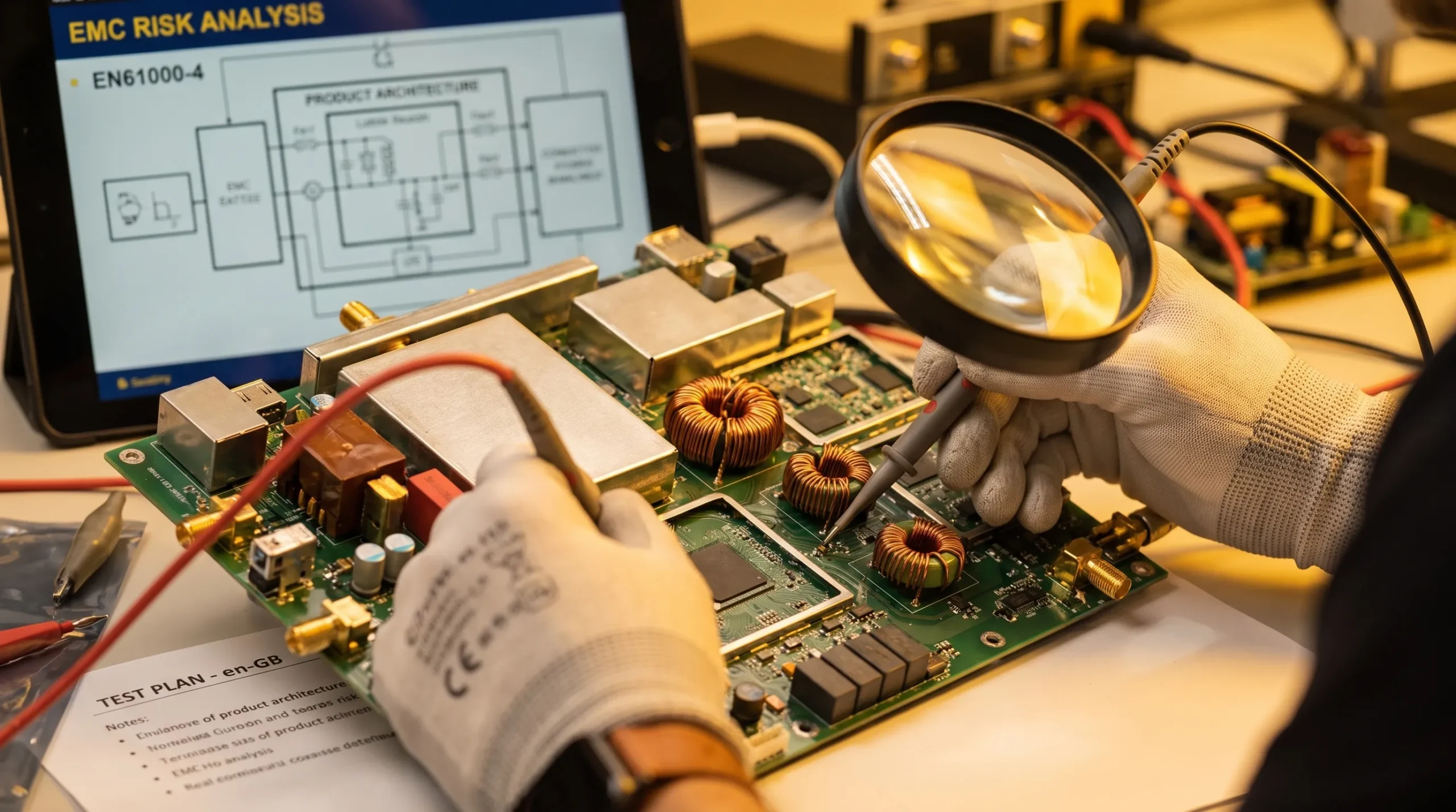
Emissions and immunity in real products
The emissions side of EMC asks whether the product disturbs its environment. This can happen through conducted emissions on power or signal lines, or through radiated emissions from PCB structures, cables or enclosures. High-speed digital electronics, switched-mode power supplies, motor drives and radio modules all need careful integration.
The immunity side asks whether the product can tolerate disturbance. In real use, disturbances may come from electrostatic discharge, electrical fast transients, surge events, nearby transmitters, switching loads, motors, relays or other electronic systems. The exact test requirements depend on the product category, market and intended environment, but the design principle is consistent: the product should have appropriate robustness for its use case.
This matters because many modern products combine multiple EMC-sensitive technologies in a compact form. A connected industrial sensor may include analogue measurement, a microcontroller, wireless communication, battery charging and a switching regulator. A robotic subsystem may combine encoders, motor control, high-current power stages, safety-related signals and communication buses. A maritime or defence product may need to remain reliable in an electrically complex environment where access for maintenance is limited.
In these products, EMC is not isolated from embedded software, mechanical design or power design. Firmware can influence emissions through PWM timing, processor load, sleep modes and communication bursts. Enclosure design can support shielding and bonding, or unintentionally create apertures and resonance paths. Connector placement can reduce or increase coupling. Manufacturing variation can also affect repeatability if EMC-critical details are not controlled.
That is why ProMicro treats EMC as part of wider embedded system design, not only as a final test topic. Early embedded design decisions that affect EMC, safety and lifecycle can influence whether a product remains robust beyond the first prototype.
A practical EMC-aware development approach
An EMC-aware process does not mean slowing development with unnecessary bureaucracy. It means making better decisions at the points where changes are still relatively efficient. The goal is to reduce uncertainty before it becomes expensive.
A practical approach usually starts with the intended operating environment. A product for a factory floor, vehicle, vessel, defence application or consumer environment will face different disturbances and regulatory expectations. The design team should understand nearby equipment, cable lengths, power sources, installation conditions, user handling, enclosure constraints and service life expectations.
From there, the engineering team can translate the environment into design requirements. These requirements guide architecture, component choices, protection circuits, grounding, layout and mechanical integration. They also help avoid vague assumptions such as assuming that a short internal cable in the prototype will behave like a long external cable in the final machine.
A structured EMC-aware development flow often includes these steps:
- Define the electromagnetic environment: Identify expected disturbances, nearby systems, cable lengths, supply conditions and installation context.
- Choose an architecture that separates risk areas: Keep noisy power stages, radios and clocks away from sensitive analogue and low-level interfaces where possible.
- Design PCB layout with return paths in mind: Treat current loops, reference planes, decoupling and routing as core design constraints.
- Integrate enclosure and cabling early: Consider shielding, bonding, connector positions, cable exits and mechanical constraints before prototype freeze.
- Measure during prototyping: Use early measurements or pre-compliance testing to find trends before formal testing.
- Document EMC-critical design choices: Capture layout rules, component alternatives, assembly details and manufacturing controls that affect repeatability.
Pre-compliance measurements are especially useful because they provide evidence while design changes are still realistic. They do not replace formal testing by an accredited laboratory where required, and they do not guarantee a final pass. They do, however, help identify obvious risks, compare design options and reduce the chance of discovering fundamental issues only at the end.

Common misconceptions about EMC meaning in design
Because EMC is often associated with compliance testing, teams sometimes underestimate how deeply it is connected to design quality. The following misconceptions are common in product development discussions.
| Misconception | Why it creates risk | Better engineering view |
|---|---|---|
| EMC is only a lab test | The design may be too mature to change efficiently by test time | EMC should influence architecture, layout and integration early |
| Shielding will fix it later | Shielding can be costly, incomplete or impractical if not designed in | Reduce disturbance at the source and control coupling paths first |
| It is only a PCB layout problem | Cables, enclosure, firmware, grounding and power design also matter | Treat EMC as a system-level property |
| Low-voltage products have no EMC risk | Low voltage circuits can still emit noise or be susceptible to disturbance | Consider switching speed, cable length, sensitivity and environment |
| If the prototype works, EMC is fine | Bench tests may not represent the real electromagnetic environment | Validate under realistic conditions and plan pre-compliance checks |
These misconceptions are not signs of poor engineering. They usually arise because teams are under time pressure and because early prototypes naturally focus on functionality. The problem is that functionality alone does not prove robustness, compliance readiness or production suitability.
Questions decision-makers should ask early
For CEOs, CTOs, technical directors and product development managers, EMC does not require reviewing every layout detail personally. It does require asking the right questions early enough that the answers can still shape the design.
Useful questions include:
- What electromagnetic environment will the product operate in during normal use?
- Which internal functions are likely noise sources, and which are likely sensitive victims?
- Are cables, connectors and the enclosure included in the EMC design discussion?
- Do firmware timing, motor control or wireless communication create EMC-relevant behaviour?
- Which standards, directives or customer requirements may apply in the target market?
- What pre-compliance checks are planned before formal testing?
- Which design details must be controlled when moving from prototype to production?
These questions help expose hidden requirements. They also help align electronics, embedded software, mechanical design, testing and manufacturing preparation. That alignment is particularly important when a product combines sensors, motor drives, wireless connectivity, analogue electronics and power conversion in one compact system.
Frequently asked questions
What does EMC mean in product design? EMC means electromagnetic compatibility. In product design, it means creating electronics that do not cause unacceptable electromagnetic disturbance and that can operate reliably when exposed to disturbances expected in their real environment.
What is the difference between EMC and EMI? EMI means electromagnetic interference, usually referring to the disturbance itself. EMC is the broader compatibility objective, covering both limiting emissions and ensuring immunity against interference.
When should EMC be considered in development? EMC should be considered from the concept and architecture phase. Early decisions about power topology, PCB layout, enclosure design, cabling, grounding and firmware behaviour can strongly influence the final result.
Can embedded software affect EMC? Yes. Firmware can influence switching patterns, PWM timing, processor activity, communication bursts, sleep modes and recovery behaviour after disturbance. EMC is not only a hardware issue.
Does pre-compliance testing guarantee certification success? No. Pre-compliance testing helps identify risks and compare design choices before formal testing, but it does not replace required certification or accredited laboratory testing where applicable.
Why involve an electronics design partner for EMC? An experienced design partner can help identify hidden EMC risks early, connect hardware and software decisions, support PCB and system-level design, and prepare products more effectively for testing, manufacturing and long-term use.
Design electronics with EMC in mind from the start
EMC meaning in product design is ultimately about creating electronics that work reliably in the real world, not only on the bench. For professional products, the cost of late EMC problems can be high: redesign effort, delayed certification, field issues and reduced confidence in the product.
ProMicro supports companies with embedded systems, power electronics, analogue electronics, PCB design, system engineering, prototyping and preparation for volume manufacturing. If your team is developing a machine, connected device, sensor system, motor drive or high-value electronic product, work with ProMicro to reduce technical risk and design with reliability, compliance and manufacturability in mind from the beginning.
