
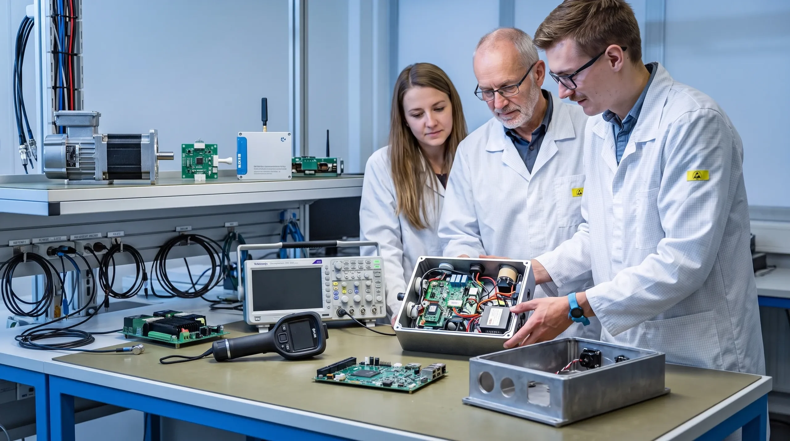
Embedded system examples are often used to explain a basic definition: a thermostat, a car control unit or a washing machine controller. That is useful, but it is not the most valuable lesson for product development teams.
For engineering managers, CTOs and product owners, examples reveal something more practical. They show how design choices in hardware, firmware, power electronics, PCB layout, enclosure design and compliance planning shape the reliability of a real product. A simple example can expose hidden requirements long before the first schematic is drawn.
An embedded system is a dedicated computing and electronics system built into a product to control a defined function. If you want the foundation first, ProMicro has a practical explanation of what embedded systems are and why they matter in products. This article takes the next step: what embedded system examples reveal about better product design.
Why examples are more useful than definitions
A definition explains what an embedded system is. An example shows what can go wrong if the product context is not understood.
A motor controller in a robot is not just a microcontroller running a control loop. It must deal with current peaks, temperature rise, electromagnetic interference, sensor feedback, safe stopping and mechanical vibration. A connected maritime sensor is not just a wireless module with firmware. It must survive moisture, salt, supply variation, radio constraints, installation errors and long service intervals.
This is why the search intent behind “what is embedded system examples” is often broader than a simple list. Technical teams are usually trying to understand how embedded systems behave in real products, where design decisions affect certification, production, field performance and maintenance.
Examples help product teams move from abstract functionality to concrete engineering constraints. They also make it easier to discuss risk with non-specialists, because the consequences are visible: a machine stops unexpectedly, a wireless product fails RED testing, a sensor drifts over time or a power stage overheats inside an enclosure.
Embedded system examples and the design lessons behind them
The value of an example is not the category itself. It is the product design lesson behind it.
| Embedded system example | Typical product role | What it reveals about product design |
|---|---|---|
| Motor drive controller | Controls speed, torque and direction in a machine, vehicle or robot | Power electronics, firmware timing, thermal design and EMC must be developed together |
| Smart sensor module | Measures pressure, temperature, vibration, position or flow | Accuracy depends on analogue design, calibration, mounting, noise control and long-term stability |
| Connected IoT device | Sends data through Wi-Fi, Bluetooth, LTE-M, LoRa or another radio technology | Connectivity affects power budget, antenna placement, enclosure design, security, RED and CE considerations |
| Automotive or off-road controller | Manages vehicle functions under harsh operating conditions | Vibration, temperature, transients, diagnostics and serviceability influence the architecture |
| Maritime or defence electronics | Operates in demanding environments with high reliability expectations | Moisture, corrosion, EMC exposure, supply quality and lifecycle support must be considered early |
| Embedded power supply or converter | Converts, regulates or distributes power inside a product | PCB layout, component selection, protection, efficiency and heat dissipation are product-level concerns |
| Laboratory or high-tech instrument | Controls measurement, actuation, user interfaces and data handling | Precision depends on signal integrity, analogue front ends, firmware behaviour and mechanical integration |
These examples show why embedded system design is rarely just “adding electronics” to a product. It is a system engineering problem in which software decisions affect hardware, mechanical decisions affect RF performance and power choices affect reliability.
Lesson 1: the visible function is only part of the requirement
Most product ideas begin with visible behaviour. A valve must open and close. A motor must move a carriage. A sensor must send a reading. A battery product must run for a certain number of hours. These are valid starting points, but they are not enough to design a robust embedded system.
A motor drive example reveals this clearly. The stated requirement may be “control a 24 V motor”. The real design requirement may include start-up current, stall detection, safe braking, encoder feedback, thermal protection, fault logging, cable length, operator safety and behaviour after a power interruption.
The same applies to a smart sensor. The stated requirement may be “measure temperature”. The real design requirement may include measurement accuracy across the full operating range, analogue noise immunity, sensor self-heating, calibration method, condensation, field replacement and drift over years of use.
Good embedded design turns product intent into verifiable behaviour. That means asking not only what the product must do, but how it must behave when conditions are imperfect.
Lesson 2: the application environment changes the architecture
A prototype on a bench can hide problems that appear immediately in a machine, vehicle, vessel or production line. The embedded system example matters because each environment applies different stresses.
A machine manufacturing application may involve motors, relays, long cables, inductive loads and switching noise. A maritime product may face moisture, salt, vibration, installation variation and limited service access. A high-tech instrument may demand low-noise analogue performance, stable timing and clean power distribution. A defence product may require a more rigorous view of robustness, supply conditions and lifecycle risks.
These environmental factors influence architecture. They affect connector choice, PCB stack-up, grounding concept, enclosure design, filtering, thermal paths, watchdog strategy, diagnostics and firmware recovery behaviour. A design that works in a plastic housing on a desk may not survive a metal enclosure near a motor drive.
For a deeper look at this topic, ProMicro also covers embedded systems and applications in demanding real-world use, including the role of heat, vibration, EMC and production variation.
Lesson 3: power electronics and embedded control are one design problem
Motor drives, DC-DC converters, battery systems, solenoid drivers and lighting controllers show why power electronics should not be treated as a separate block added late in the project.
In many products, firmware controls switching behaviour, current limits, fault responses and operating modes. The PCB layout determines parasitic effects, noise coupling, thermal performance and measurement quality. The analogue front end determines whether current, voltage and temperature readings can be trusted. The enclosure determines whether heat can leave the product.
If these disciplines are separated too strongly, the product may pass a basic functional test but fail under load, temperature or EMC stress. A stable embedded system requires alignment between control algorithms, gate driving, sensing, grounding, filtering, protection circuits and mechanical packaging.
This is particularly relevant in robotics, machine control, automotive subsystems and industrial equipment, where embedded software directly influences physical movement, energy conversion or operator safety.
Lesson 4: connectivity turns the product into a lifecycle system
A connected embedded system is not just a conventional product with a radio module. Wireless communication changes the product architecture.
Antenna position may be affected by the enclosure, display, PCB ground plane, battery, cabling or mounting location. Power consumption may change depending on network behaviour. Firmware updates may become part of long-term support. Product variants may need different regional radio configurations. Diagnostics may need to help service teams distinguish between sensor faults, network faults and installation problems.
Compliance should also be considered from the concept stage. The European Commission’s CE marking guidance explains the general framework for products placed on the European market, while the Radio Equipment Directive is especially relevant when a product intentionally transmits or receives radio waves.
Designing with EMC, RED and CE requirements in mind does not guarantee a smooth certification path, but it reduces the risk of discovering avoidable problems after the enclosure, PCB and firmware architecture are already fixed.
How examples help teams define better requirements
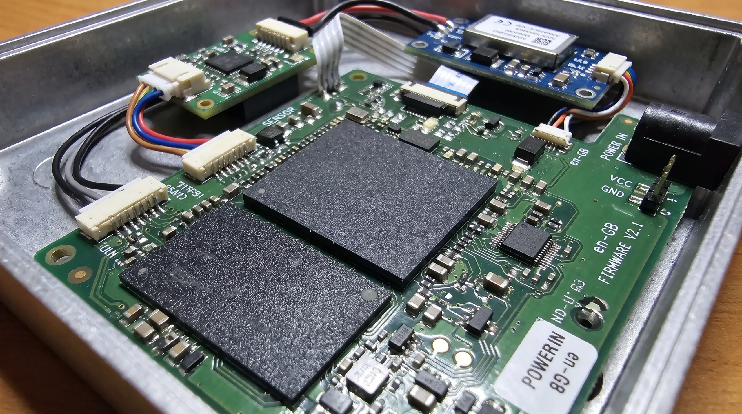
An embedded system example becomes a useful design tool when it is translated into questions. Instead of copying an existing solution, the team uses the example to uncover product-specific constraints.
| Requirement area | Questions an example should trigger |
|---|---|
| Function and control | What operating modes, edge cases, fault states and recovery behaviours are required? |
| Environment | What temperature, vibration, moisture, dust, EMC and installation conditions will the product face? |
| Power | What supply variation, inrush current, protection, efficiency and thermal constraints apply? |
| Interfaces | Which sensors, actuators, displays, connectors, wireless links or external systems must interact reliably? |
| Firmware | How will timing, diagnostics, updates, watchdogs, data logging and calibration be handled? |
| Compliance | Which EMC, RED, CE, safety or sector-specific requirements should influence the design concept? |
| Manufacturing | How will the product be assembled, tested, programmed, calibrated and maintained at volume? |
| Lifecycle | Which components, firmware tools, documentation and service processes must remain supportable? |
This type of structured thinking is especially valuable when internal teams are under pressure to move quickly. Early clarity reduces the chance of expensive redesigns after prototype testing, compliance pre-checks or production preparation.
Prototype success does not prove production readiness
Many embedded system examples work well as first prototypes. That does not mean they are ready for volume manufacturing.
A prototype is often built to prove a function. A production-ready embedded product must also be manufacturable, testable, repeatable, serviceable and maintainable. It needs a stable bill of materials, controlled PCB layout, documented firmware release process, test strategy, calibration approach and mechanical integration that can tolerate production variation.
This difference becomes visible in examples such as connected sensors and power converters. A sensor prototype may perform well when assembled by the development team, but production units may show variation due to component tolerances, enclosure pressure, mounting differences or calibration gaps. A power converter may operate correctly at room temperature, but fail when tolerances, maximum load and enclosure heat are combined.
Design for manufacturing and design for test should therefore be part of embedded system development, not a separate activity at the end. Test points, programming access, serial number handling, fault logs, connector accessibility and calibration fixtures can all influence PCB and enclosure decisions.
Common mistakes that examples reveal
Embedded system examples often expose the same design mistakes across industries. They are not always caused by a lack of technical skill. More often, they come from incomplete requirements, late integration or underestimating the product environment.
Common mistakes include:
- Treating the PCB as the complete product instead of part of a wider system with firmware, power, mechanics and compliance constraints
- Selecting a microcontroller, radio module or power component before the operating modes and lifecycle requirements are clear
- Leaving EMC, RED or CE considerations until the prototype is already mechanically and electrically locked
- Designing firmware around the ideal case, with too little attention to fault handling, diagnostics and recovery behaviour
- Using a bench power supply during development without testing supply variation, transients, brownouts and cable effects
- Underestimating the influence of enclosure material, grounding, connector placement and antenna position
- Building a functional prototype without planning how it will be tested, programmed and calibrated in production
The cost of these mistakes is rarely limited to the engineering task itself. A late PCB change can trigger enclosure changes, firmware changes, new testing, supplier delays and renewed compliance uncertainty. That is why early system-level thinking is often cheaper than late correction, even when the initial design phase takes more discipline.
What embedded system examples reveal for different industries
The same embedded principles apply across markets, but the priority shifts by application.
In machine manufacturing, embedded systems often need to control motion, monitor sensors, communicate with industrial networks and survive electrical noise. Reliability, service access and predictable behaviour during faults are central.
In robotics, the interaction between motor control, sensors, battery management and safety behaviour is particularly important. Small timing errors or poor noise control can create unstable movement or unreliable feedback.
In maritime and defence applications, robustness, supply variation, moisture, vibration, EMC exposure and lifecycle planning often carry more weight than feature density. Maintenance windows may be limited and product availability may need to be managed over long periods.
In automotive and mobility applications, embedded products must be designed with transients, temperature extremes, vibration, diagnostics and repeatable production in mind. Even non-safety-critical subsystems benefit from a disciplined approach to fault handling and validation.
In consumer electronics for professional or high-value markets, cost, usability and manufacturability still matter, but so do wireless performance, battery life, product feel, firmware updates and support over the product lifecycle.
ProMicro’s article on the application of embedded system in machines, vehicles and devices explores these application differences in more detail.
When to involve an electronics design partner
An external electronics design partner adds the most value before the architecture is fixed. At that stage, choices around microcontrollers, sensors, power topology, PCB layout, enclosure strategy, connectors, firmware structure and compliance planning can still be aligned.
This is particularly useful when a company has a strong product idea but limited specialist capacity in embedded systems, analogue electronics, power electronics or manufacturing preparation. It is also relevant when internal engineers are already fully occupied with core product development and need additional depth for a complex subsystem.
The right partner should not only execute a requested task. They should help identify hidden requirements, challenge risky assumptions and connect product behaviour with real-world constraints. In embedded system design, that wider view is often the difference between a prototype that demonstrates a feature and a product that can be manufactured, certified, maintained and used reliably.
Frequently asked questions
What are embedded system examples in product design? Embedded system examples include motor controllers, smart sensors, automotive control units, connected IoT devices, power converters and industrial machine controllers. In product design, they are useful because they show how hardware, firmware, power, interfaces and environment work together.
How do embedded system examples reduce development risk? They help teams identify hidden requirements early, such as EMC exposure, thermal limits, supply variation, fault handling, calibration, production testing and lifecycle support. This reduces the chance of late redesigns.
Why do embedded prototypes fail in real-world use? Prototypes often focus on function under controlled conditions. Real-world products face vibration, heat, moisture, electrical noise, user variation, supply transients, production tolerances and compliance constraints.
Should EMC, RED and CE be considered before or after prototyping? They should influence the design concept before the first prototype. Formal testing may come later, but early choices in layout, enclosure, grounding, filtering, antenna placement and component selection strongly affect compliance risk.
Is embedded system design mainly a software task? No. Embedded system design combines firmware, electronics, power, analogue design, PCB layout, interfaces, mechanics, testing and manufacturing preparation. Software is central, but it cannot be separated from the physical product.
Turn examples into a stronger product design approach
Embedded system examples are most valuable when they change how a team designs. They reveal hidden requirements, integration risks and lifecycle decisions that are easy to miss when the focus stays on the visible function.
If your organisation is developing a machine, connected device, power electronics product or high-value technical system, ProMicro can support the journey from concept and prototype to production-ready electronics. The team combines embedded systems, power electronics, analogue design, PCB design, enclosure thinking, prototyping and volume manufacturing support in one development process.
To discuss a product idea, technical challenge or embedded electronics roadmap, visit ProMicro and explore how a system-level development partner can help reduce risk before design choices become expensive to change.
