
Certification delays rarely start at the test house. In most embedded products, they begin much earlier, when architecture, PCB layout, firmware behaviour, cabling, enclosure choices and component selection are still being defined.
For technical directors, engineering managers and product owners, this is an important distinction. A failed EMC test, RED assessment or safety review may look like a late-stage problem, but the root cause is often an early embedded system design decision that was never checked against the real operating environment.
In this article, “certification” refers broadly to CE conformity assessment, EMC and RED testing, safety-related evaluation, customer qualification and other approval steps that professional electronic products may need before market introduction. Not every product requires the same route, and CE marking is often based on the manufacturer’s declaration supported by technical evidence. However, the same principle applies: compliance must be designed into the system, not inspected in at the end.
Why embedded system design mistakes delay certification
Embedded products are no longer simple control boards. A modern device may combine sensors, motor drives, wireless communication, high-speed digital interfaces, power conversion, analogue measurement, cloud connectivity and mechanical integration in one compact system.
That integration creates many paths to certification delay. A motor drive can disturb a radio module. A DC/DC converter can inject noise into an analogue sensor. A cable shield may work in the lab but fail in the final enclosure. A firmware update can change radio duty cycle, thermal load or power sequencing. A component substitution can alter emissions or safety margins.
The challenge is not only to make the product function. The challenge is to make it function reliably, repeatedly and measurably under real installation conditions, with a design file that supports testing, documentation and production.
ProMicro has written separately about what EMC is and why it matters. Here, we focus on the design mistakes that commonly push certification timelines out by weeks or months.
Mistake 1: treating certification as a final project phase
One of the most common embedded system design mistakes is planning certification only after the prototype works. This is understandable, especially when teams are under pressure to prove the concept quickly. But it creates a dangerous sequence: first make it work, then try to make it compliant.
By that point, many critical choices are already locked in. The PCB stack-up may be fixed. Connector positions may be frozen by the enclosure. Antenna location may be constrained by mechanical design. Firmware architecture may not support the operating modes required for testing. Power electronics may already be too noisy for the chosen cabling and housing concept.
A better approach is to define a compliance strategy during system architecture. This does not mean testing everything on day one. It means identifying the likely directives, standards, market requirements and worst-case operating modes before the design becomes expensive to change.
A practical early compliance plan should clarify:
- Target markets and applicable regulatory frameworks, such as CE, UKCA, EMC, RED or product-specific safety requirements.
- Product classification and intended use, including professional, industrial, maritime, defence-related or consumer-facing contexts.
- Interfaces that create compliance risk, including mains input, batteries, motors, antennas, external cables and high-speed communication.
- The evidence needed for the technical file, such as schematics, PCB data, risk analysis, test reports, manuals and production control.
- Which design reviews, simulations or pre-compliance tests should happen before formal testing.
This early plan reduces uncertainty. It also helps management understand that certification is not a single milestone, but a design constraint throughout the development process.
Mistake 2: underdefining the real operating environment
A prototype can behave perfectly on a clean lab bench and still fail in the field. Certification delays often appear when the test conditions reveal an environment that was not fully described in the requirements.
Professional electronic products may be installed in machines, vehicles, cabinets, vessels, outdoor housings, mobile assets or production lines. For example, test equipment, battery systems or communications units may be deployed in vehicle cabins, steel cabinets or commercial shipping containers, where airflow, grounding, humidity and temperature rise differ significantly from a standard office or lab environment.
These installation details matter because compliance is system-level. EMC behaviour depends on cables, bonding, enclosure seams, grounding and nearby equipment. Thermal behaviour depends on mounting orientation, ventilation and duty cycle. Wireless performance depends on antenna placement, metal structures and coexistence with other radio systems.
| Environment factor | Why it affects certification | Design implication |
|---|---|---|
| Long external cables | Can act as antennas for emissions and immunity coupling | Define cable length, shielding and connector strategy early |
| Metal enclosures or machine frames | Influence grounding, bonding and antenna performance | Treat mechanical integration as part of the electrical design |
| Motor drives and inductive loads | Create fast transients, conducted noise and radiated emissions | Design switching behaviour, filtering and PCB layout together |
| Outdoor or maritime conditions | Add humidity, corrosion, temperature cycling and vibration | Select components, coatings and enclosures for the environment |
| Battery or vehicle power | Introduces brownouts, load dumps, reverse polarity and inrush | Include input protection, diagnostics and fault handling |
The mistake is not failing to predict every detail. The mistake is treating the application environment as secondary. Hidden requirements around installation, maintenance, cable routing and user behaviour often become visible only when certification or field testing exposes them.
Mistake 3: assuming a certified module makes the whole product compliant
Using a pre-certified radio module, power supply or communication module can reduce risk. It does not automatically make the final product compliant.
This is especially relevant for connected embedded systems using Bluetooth, Wi-Fi, cellular, LoRa, GNSS or other radio technologies. The final product still has its own antenna configuration, enclosure, ground plane, firmware settings, power supply noise, coexistence behaviour and installation instructions. Any of these can affect RED, EMC or safety-related assessment.
For products placed on the EU market, the European Commission’s Radio Equipment Directive information is a useful starting point for understanding the regulatory scope. Since August 2025, additional RED cybersecurity, privacy and fraud protection requirements have also become relevant for many categories of internet-connected radio equipment. That means firmware, update mechanisms and connectivity choices are increasingly part of compliance discussions, not just hardware design topics.
Common module-related mistakes include selecting the module before defining the antenna environment, changing the antenna without checking the module approval conditions, ignoring regional radio variants, or failing to lock firmware parameters such as output power, duty cycle and channel use.
The safer design approach is to treat a module as a component in the compliance strategy, not as a shortcut around it. The final product still needs system-level verification.
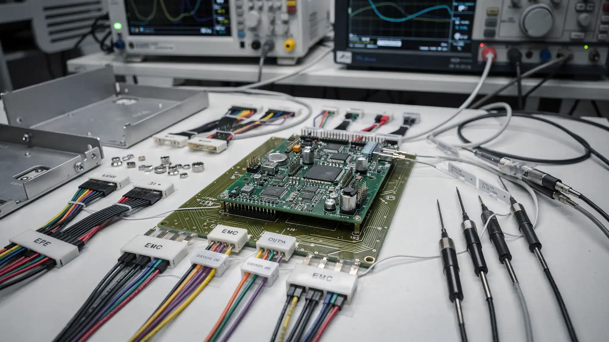
Mistake 4: separating PCB layout from EMC, power and enclosure decisions
PCB layout is often where certification risk becomes physical. Routing, return paths, grounding, layer stack-up, component placement and connector position can determine whether a product is quiet, robust and testable.
In embedded products with power electronics, motor drives or high-speed interfaces, small layout decisions can have large EMC consequences. A switching node placed near an analogue input can degrade measurement stability. A discontinuous return path can increase loop area. A poor shield termination can turn a cable into an efficient radiator. A connector placed for mechanical convenience can create an avoidable emissions path.
The problem is amplified when PCB layout, enclosure design and firmware are handled as separate workstreams without enough system-level review. EMC is not solved only with filters added at the end. Filters can help, but they cannot fully compensate for poor current loops, unstable power architecture or unplanned coupling paths.
A certification-aware layout process considers:
- Current loops for high di/dt and high dv/dt signals.
- Separation between noisy power sections and sensitive analogue or RF sections.
- Controlled impedance and return paths for high-speed communication.
- Cable entry points, shield bonding and connector grounding.
- Thermal paths for power components and regulators.
- Test points for debug, production verification and certification modes.
This is why embedded system design should integrate electronics, power, analogue and mechanical thinking early. A PCB is not just a carrier of components. It is part of the electromagnetic, thermal and mechanical behaviour of the product.
Mistake 5: building prototypes that are not representative enough
Early prototypes are meant to answer questions. They do not need to be perfect. But when a prototype is used to make certification or launch decisions, it must be representative of the final product in the areas that matter.
Development boards, flying leads, bench power supplies and open enclosures are useful for proving algorithms or sensor principles. They are weak indicators of final EMC, thermal behaviour, safety spacing, radio performance and manufacturability. A design can appear low risk because the prototype works, while the production-intent system still contains unresolved compliance risks.
This becomes a serious schedule issue when the first “real” integrated prototype is also the version sent to the test house. If it fails, the redesign may affect PCB layout, enclosure tooling, cable assemblies, firmware and documentation at the same time.
For professional products, it is better to plan prototype maturity intentionally. Early prototypes can validate feasibility. Later prototypes should validate system integration. Pre-compliance builds should be close enough to the production design to make the results meaningful.
A useful question for every prototype review is: what certification risk can this prototype actually reduce? If the answer is unclear, the prototype may still be valuable, but it should not create false confidence.
Mistake 6: not designing firmware for testability and safe behaviour
Certification is often discussed as a hardware topic, but firmware can be a major cause of delay. Many tests require controlled operating modes that normal user workflows do not provide.
For example, EMC testing may need the product to transmit continuously, drive motors at worst-case load, switch power stages in defined states, exercise all I/O ports, log faults or remain in a repeatable operating mode for long periods. RED testing may require specific radio settings. Safety-related assessment may require predictable behaviour during brownouts, sensor faults, communication loss or watchdog resets.
If firmware does not support these modes, the team may need to create special test builds late in the project. That introduces new risk: the tested firmware may no longer be the same as the production firmware. Changes made to pass a test can also affect timing, power consumption, thermal load or communication behaviour.
Certification-ready firmware design includes stable version control, diagnostic modes, repeatable test commands, clear configuration management and defined safe states. It also includes documentation of how the product behaves during faults, start-up, shutdown and recovery.
For connected products, firmware design also intersects with security and lifecycle obligations. Update mechanisms, access control, default credentials, logging and vulnerability handling are increasingly relevant to product acceptance and market access, particularly for IoT and radio-enabled products.
Mistake 7: underestimating power electronics and analogue behaviour
Power electronics and analogue circuits often create certification surprises because they connect the ideal digital design to the messy physical world.
A DC/DC converter is not just a power block. Its switching frequency, layout, compensation, load transients and thermal conditions can influence emissions and stability. A motor driver is not just an actuator interface. Its switching edges, cable length, braking behaviour and fault current paths can dominate EMC results. An analogue sensor front end is not just an input. Its filtering, grounding and reference stability affect measurement reliability under immunity stress.
Design mistakes in these areas can delay certification because fixes are rarely isolated. Reducing emissions may require layout changes, not just a larger filter. Improving immunity may require input protection, better grounding and firmware fault handling. Solving thermal derating may require a different enclosure, heatsinking strategy or power architecture.
This is where system-level trade-offs are essential. Lower switching losses, better efficiency, smaller size, lower cost and lower emissions do not always point to the same design choice. The right answer depends on the product’s operating profile and compliance priorities.
Mistake 8: weak requirements traceability and documentation
A test house can only test what is defined. A manufacturer can only justify conformity with evidence. If requirements, design decisions and configurations are not traceable, certification can stall even when the hardware performs well.
Documentation gaps often appear late because engineering teams focus on solving technical problems first. But missing information can delay test planning, technical file preparation, user manual review, production release and supplier communication.
Typical documentation issues include unclear product variants, undocumented cable options, incomplete BOM status, missing firmware version references, incomplete risk analysis, unclear installation instructions or unresolved component substitutions.
A robust certification package is built throughout development. It should connect requirements to architecture, design outputs, verification results and production controls. This is not bureaucracy for its own sake. It protects the project from ambiguity when a test fails, a component changes or a customer asks for evidence.
The same principle applies to risk management in complex product development. ProMicro discusses this broader topic in how embedded systems reduce risk in complex product development.
Mistake 9: ignoring manufacturing variation until after approval
A single compliant prototype is not the same as a compliant product in volume manufacturing. Certification delays can occur when the design passes in one configuration but cannot be built consistently.
Manufacturing variation affects component tolerances, cable assemblies, enclosure materials, connector plating, thermal interfaces, antenna placement, coating thickness and PCB supplier processes. Even approved substitutions can alter EMC behaviour or safety margins if they are not controlled.
This is why manufacturing readiness should be connected to certification planning. Production test strategy, critical component control, supplier quality and lifecycle management all influence whether the approved design remains stable over time.
A production-ready embedded system should define which parts are critical for compliance, which substitutions need engineering review, which parameters must be tested in production and which configuration was used for formal testing. Without this control, a product can drift away from its approved state after launch.
A practical pre-certification checklist for embedded products
Before sending an embedded product for formal testing, engineering leaders should be able to answer the following questions with confidence:
- Have the applicable standards, directives and market requirements been identified for the product and its variants?
- Are the PCB, enclosure, cables, antennas and power supply representative of the intended production configuration?
- Have worst-case operating modes been defined for EMC, RED, thermal and safety-related testing?
- Does the firmware include controlled test modes, diagnostics and stable version management?
- Have power electronics, analogue interfaces and wireless modules been reviewed at system level?
- Has pre-compliance testing been performed early enough to allow meaningful redesign if needed?
- Are critical components, BOM alternatives and production test requirements documented?
- Are installation instructions, user constraints and environmental assumptions clear?
If several answers are uncertain, the project may not be ready for formal certification testing. In that case, a focused design review or pre-compliance phase can be faster and cheaper than entering the test lab too early.
Common delay triggers and how to prevent them
| Delay trigger | Typical root cause | Prevention method |
|---|---|---|
| EMC failure late in development | Layout, grounding, cabling or enclosure decisions made without EMC review | Include EMC design reviews and pre-compliance testing before final PCB release |
| RED or wireless retesting | Antenna, enclosure or firmware settings changed after module selection | Define radio configuration and antenna integration early |
| Thermal failure during testing | Prototype tested at low duty cycle or open bench conditions | Test worst-case load, enclosure and ambient temperature before formal approval |
| Safety documentation delay | Missing risk analysis, manuals or component evidence | Build the technical file alongside development |
| Firmware mismatch | Test firmware differs from production firmware | Use controlled test modes within a managed production codebase |
| Production drift | Uncontrolled substitutions or supplier variation | Define compliance-critical components and production verification steps |
The objective is not to eliminate every risk. That is unrealistic in complex electronics development. The objective is to expose the right risks early, when architecture and design choices can still be adjusted without major programme impact.
Frequently asked questions
When should certification be considered in embedded system design? Certification should be considered during the requirements and architecture phase, before PCB layout and enclosure constraints are fixed. Early planning helps identify EMC, RED, safety, thermal, firmware and documentation requirements that influence the design.
Does a certified wireless module guarantee RED or CE compliance for the final product? No. A certified module can reduce risk, but the final product still needs system-level assessment. Antenna integration, enclosure design, firmware settings, power supply noise and installation instructions can all affect compliance.
What is pre-compliance testing? Pre-compliance testing is an early, targeted evaluation that uses test methods similar to formal compliance testing to find design weaknesses before the official test campaign. It does not replace formal testing, but it can reduce the risk of late redesign.
Can firmware really delay certification? Yes. Firmware controls operating modes, radio behaviour, power states, diagnostics, fault handling and test repeatability. If test modes or version control are missing, teams may lose time creating special builds or explaining which software version was actually tested.
Why involve an external electronics design partner before certification? A specialist partner can review the full system, including embedded hardware, firmware behaviour, power electronics, analogue interfaces, PCB layout, enclosure integration and production readiness. This helps identify hidden risks before they become certification delays.
Design certification readiness into the product from the start
Certification delays are often symptoms of earlier design uncertainty. The most effective way to reduce them is to bring compliance thinking into requirements, architecture, PCB design, firmware, enclosure integration, prototyping and manufacturing preparation.
ProMicro supports companies developing complex electronic products from concept to volume-ready solutions. Our work combines embedded system design, power electronics, analogue electronics, PCB design, system engineering, prototyping and lifecycle thinking, with attention to EMC, RED, CE and real-world reliability challenges.
If your team is developing a connected device, machine controller, sensor system, motor drive, maritime product, defence-related platform or high-tech electronic module, involving the right expertise early can prevent expensive redesign later.
Visit ProMicro to discuss how to make your embedded electronics more robust, scalable and ready for the next development stage.