
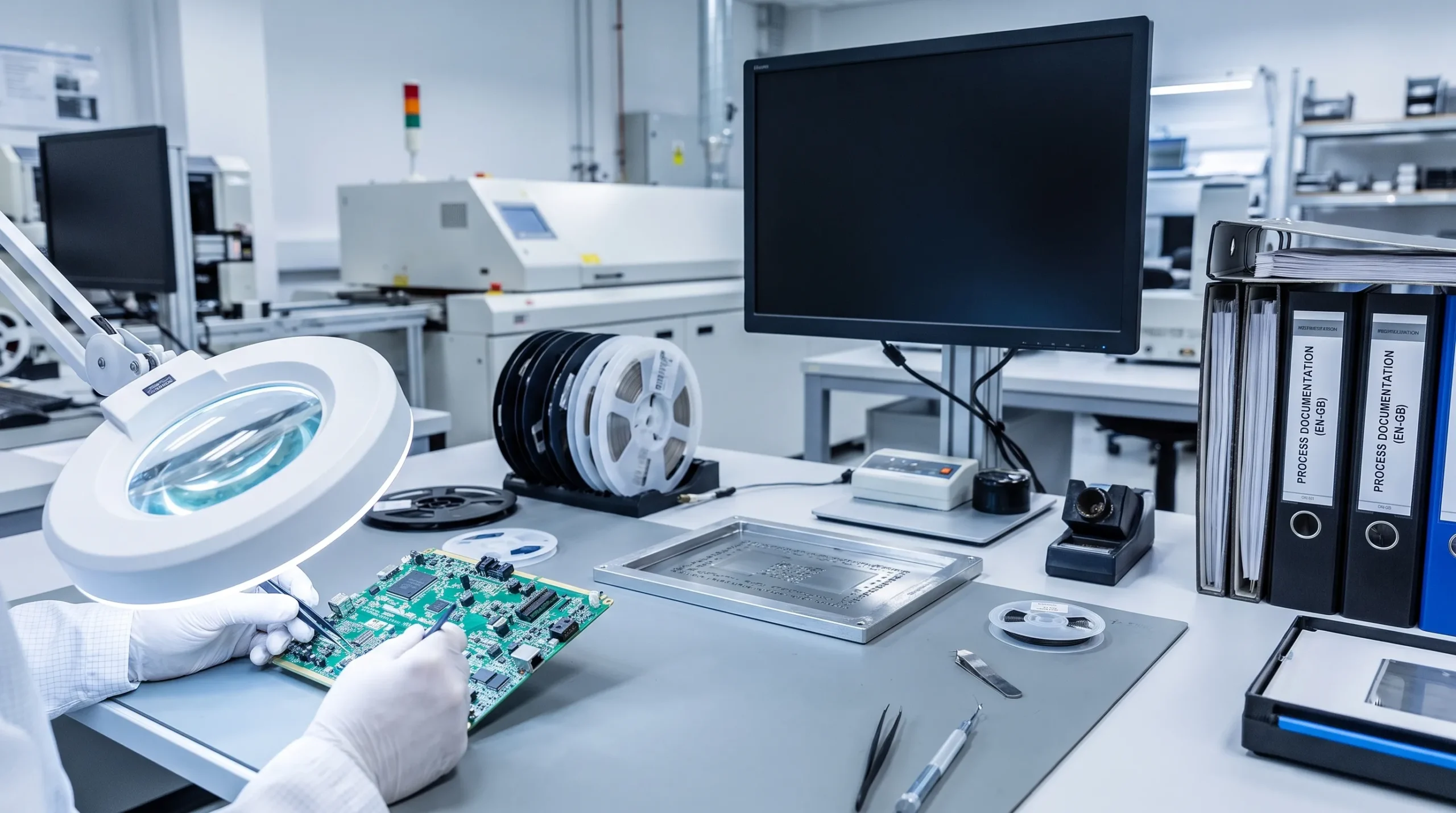
Electronics assembly is often treated as the stage after design, procurement and PCB fabrication. In practice, it is one of the clearest indicators of whether an electronic product is truly ready for the real world.
For technical directors, engineering managers and product owners, electronics assembly is not just about placing components on a board. It is where decisions about tolerances, thermal behaviour, EMC, test access, firmware loading, mechanical integration and traceability become physical. If those decisions are weak, the product may still pass a first functional test, but struggle during certification, field use or volume manufacturing.
A well-controlled assembly process helps reduce rework, improve repeatability and expose hidden risks before they become expensive. This is especially important for embedded systems, power electronics, analogue front ends, motor drives, wireless products and equipment that must operate reliably in demanding environments.
Why electronics assembly quality starts before the assembly line
The quality of electronics assembly is shaped long before solder paste is printed or a pick-and-place machine starts running. It starts with a clear understanding of the product context: where the product will be used, who will install it, what electrical loads it must handle, how it will be serviced and which compliance routes may apply.
A PCB designed for a protected indoor device has very different assembly risks from a control unit installed in a machine, vehicle, maritime application or defence-related system. Vibration, humidity, cable strain, thermal cycling, high current paths and electromagnetic interference all influence assembly choices.
That is why assembly planning should be part of the development process, not a late purchasing activity. When design, PCB layout, firmware, enclosure design and manufacturing preparation are aligned early, the assembled product has a much better chance of behaving consistently. ProMicro explores this broader relationship between design and build in its article on PCB assembly and manufacturing for reliable electronics.
Quality is repeatability. This principle applies across manufactured products, not only electronics. Whether a company is building industrial controllers or factory-built housing such as manufactured homes in San Antonio, reliable outcomes depend on controlled processes, clear specifications and disciplined assembly steps.
The electronics assembly steps that influence product quality
Each step in electronics assembly adds value, but each also introduces risk. A high-quality process is not only about inspecting at the end. It is about controlling the inputs and decisions that determine whether final inspection is likely to succeed.
| Assembly step | What must be controlled | Product quality impact |
|---|---|---|
| Requirements and assembly strategy | Product environment, compliance expectations, production volume and service needs | Prevents hidden use-case risks from being discovered too late |
| Production data preparation | BOM, Gerbers, pick-and-place data, drawings, test requirements and revision control | Reduces errors, ambiguity and delays during build |
| Component sourcing | Approved parts, lifecycle status, alternates and traceability | Improves reliability and protects against supply chain disruption |
| Bare PCB fabrication | Stack-up, material, copper thickness, surface finish and tolerances | Affects solderability, EMC, thermal behaviour and mechanical robustness |
| Solder paste and stencil design | Aperture design, paste type, stencil thickness and print control | Reduces solder bridging, insufficient joints and voiding |
| Component placement and reflow | Placement accuracy, orientation, thermal profile and component sensitivity | Determines solder joint quality and long-term reliability |
| Secondary assembly | Through-hole parts, connectors, cables, heatsinks and mechanical hardware | Influences robustness, serviceability and resistance to real-world stress |
| Inspection and test | AOI, X-ray where needed, ICT, functional test and calibration | Detects process faults before products leave the factory |
| Firmware loading and configuration | Correct firmware version, parameters, security settings and traceability | Ensures hardware and software work as a controlled product |
| Final integration | Enclosure fit, sealing, labelling, packaging and documentation | Turns a working board into a production-ready system |
Requirements and assembly strategy
The first quality step is deciding what the assembly must survive. A product with a motor drive, high-current switching stage or sensitive analogue measurement circuit needs different assembly priorities from a low-power sensor node. Wireless products may need careful antenna placement and enclosure interaction. Safety-related equipment may require additional spacing, insulation, derating and documentation discipline.
At this stage, teams should define assembly-critical requirements. These include target production volumes, expected product lifetime, field conditions, allowable repair methods, test coverage, traceability needs and compliance assumptions. The objective is not to predict every certification result, but to design with EMC, RED, CE, safety and manufacturability in mind from the beginning.
This is also where hidden requirements often appear. A cable gland may create mechanical stress on a connector. A metal enclosure may change wireless performance. A heat-producing component may affect nearby electrolytic capacitors. These risks are easier to solve before the PCB and enclosure are locked.
Production data and revision control
Even a strong design can fail in assembly if the production data is incomplete or inconsistent. The assembly partner needs more than a schematic and a PCB file. A reliable data package usually includes the bill of materials, approved manufacturer part numbers, component placement files, fabrication drawings, assembly drawings, test instructions, programming instructions and revision history.
Revision control is critical. If firmware, PCB layout, BOM and mechanical parts move independently, the assembly line can build a product that technically matches one document but fails as a system. This is a common cause of late-stage rework, especially when prototypes evolve quickly.
For complex products, the production data should also define which components are safety-critical, EMC-sensitive, calibrated, matched or not interchangeable without approval. This helps procurement and assembly teams avoid substitutions that look harmless commercially but change product behaviour.
Component sourcing and incoming control
Component choice has a direct effect on assembly quality. Package size, moisture sensitivity level, termination finish, temperature rating and lifecycle status all matter. A component that is easy to prototype by hand may be poorly suited for repeatable production, especially if it has difficult soldering characteristics or limited second-source availability.
Incoming control is not only about counting parts. It should verify that parts match the approved BOM, are stored correctly and are suitable for the assembly process. Moisture-sensitive devices may require controlled storage or baking. Connectors and mechanical parts should be checked for fit and tolerance issues. Power components may need additional attention because thermal and electrical margins are often central to product reliability.
In long-life industrial and professional products, component availability is also a quality issue. A forced redesign after a part becomes obsolete can create new EMC, thermal or firmware risks. Lifecycle thinking therefore belongs in assembly planning, not only in purchasing.
PCB fabrication choices that affect assembly
The bare PCB is the foundation of the assembly. Stack-up, laminate, copper thickness, via structure, solder mask, surface finish and panelisation affect both assembly yield and long-term reliability. Poor panel design can cause board flex during assembly. Inappropriate surface finish can reduce solderability. Insufficient copper or poor thermal relief can make solder joints difficult to control.
Power electronics and mixed-signal boards need particular care. High-current paths, isolation distances, creepage and clearance, heat spreading and sensitive analogue routing all influence how easily the board can be built and tested. A PCB can meet an electrical schematic and still be difficult to assemble consistently if these details are not considered.
For teams preparing volume builds, a structured review is useful. ProMicro’s design for manufacturing PCB checklist covers many of the topics that should be checked before committing to production.
Solder paste printing and stencil design
Solder paste printing is one of the most important steps in surface mount assembly. Many solder defects start here, even if they are only discovered after reflow. Too much paste can create bridges or solder balls. Too little paste can cause weak joints, opens or intermittent failures.
Stencil thickness, aperture geometry and paste type should match the component mix. Fine-pitch ICs, thermal pads, small passives and power packages often require different paste strategies on the same board. Thermal pad apertures, for example, may need segmentation to reduce voiding and prevent components from floating during reflow.
Process control is essential. Paste condition, printer setup, board support, cleaning intervals and inspection all affect repeatability. For high-reliability products, solder paste inspection can be valuable because it catches print defects before components are placed.
Placement, reflow and solder joint reliability
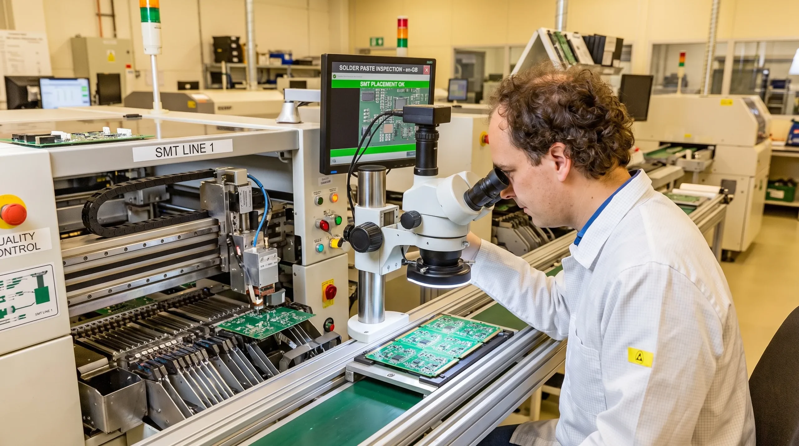
Pick-and-place accuracy affects not only whether the board works after assembly, but also how it behaves over time. Misalignment may pass electrical test but create weaker solder joints. Polarity errors, rotated components or incorrect package variants can lead to immediate failures or more subtle field issues.
The reflow profile must suit the PCB, solder paste and component set. Large copper areas, power components and heavy connectors absorb heat differently from small signal components. A profile that is too aggressive can damage parts or stress the PCB. A profile that is too mild can create poor wetting or incomplete joints.
For products exposed to vibration, thermal cycling or high current, solder joint quality is especially important. Visual inspection alone may not reveal all risks. Depending on package type, X-ray inspection may be needed for BGAs, QFNs and hidden solder joints. The goal is to understand process capability, not simply to find occasional defects.
Secondary assembly and mechanical integration
Electronics assembly does not stop when the PCB leaves the SMT line. Many quality issues appear during secondary assembly: through-hole soldering, connector installation, cable routing, heatsink fitting, enclosure mounting, sealing, labelling and final packaging.
Mechanical integration deserves particular attention in professional products. A connector mounted slightly off position may create stress when the enclosure is closed. A cable route may interfere with airflow. A heatsink may not maintain consistent pressure. A gasket may compress unevenly and affect ingress protection. These are system-level assembly issues, not isolated mechanical details.
This is why collaboration between electronics, embedded software and mechanical design is so valuable. For example, thermal behaviour depends on component selection, PCB copper, enclosure design, firmware-controlled duty cycles and the final assembly method. Treating these as separate work packages can hide risks until late testing.
Inspection, programming and functional testing
Inspection should be designed around the product risk. Automated optical inspection is useful for polarity, placement, solder defects and missing components. X-ray can reveal hidden joint issues. In-circuit testing can detect opens, shorts and component value problems. Functional testing verifies that the assembled product performs its intended tasks.
For embedded systems, firmware loading and configuration are part of the assembly quality chain. The correct firmware version, bootloader, calibration data, security keys and product settings must be controlled. If this step is informal, two visually identical products may behave differently in the field.
A robust functional test should reflect the real product architecture. Power rails, sensors, communication interfaces, motor outputs, analogue inputs, wireless functions and safety-related states may all need verification. The test does not have to duplicate full certification, but it should catch assembly faults and configuration errors before the product reaches the customer.
| Test or inspection method | Typical purpose | When it is especially valuable |
|---|---|---|
| AOI | Checks placement, polarity and visible solder defects | SMT boards with many components or fine-pitch devices |
| X-ray | Reveals hidden solder joints and voiding | BGAs, QFNs, power pads and dense assemblies |
| ICT or flying probe | Finds shorts, opens and wrong component values | Boards where electrical access is available |
| Boundary scan | Tests digital connectivity without full physical access | Complex digital boards with limited test points |
| Functional test | Confirms product behaviour under controlled conditions | Embedded systems, power electronics and connected devices |
| Calibration | Aligns measurement or control accuracy | Analogue sensors, measurement systems and control products |
| Burn-in or stress screening | Exposes early-life failures | High-value products or demanding operating environments |
Traceability and feedback loops
Traceability links every assembled product to the data needed to understand it later. This can include PCB revision, BOM revision, firmware version, component batches, assembly date, test results and calibration values. The level of traceability should match the product risk and industry expectations.
Without traceability, field failures are harder to investigate. A team may know that a product failed, but not whether it came from a specific batch, component lot, firmware version or process change. With traceability, quality improvement becomes evidence-based.
Feedback loops are equally important. Assembly yield, test failures and rework causes should be reviewed by engineering, not only by production. A repeated solder bridge may indicate a stencil issue. A recurring functional test failure may point to marginal power sequencing, poor test coverage or a firmware configuration weakness.
From prototype assembly to volume manufacturing
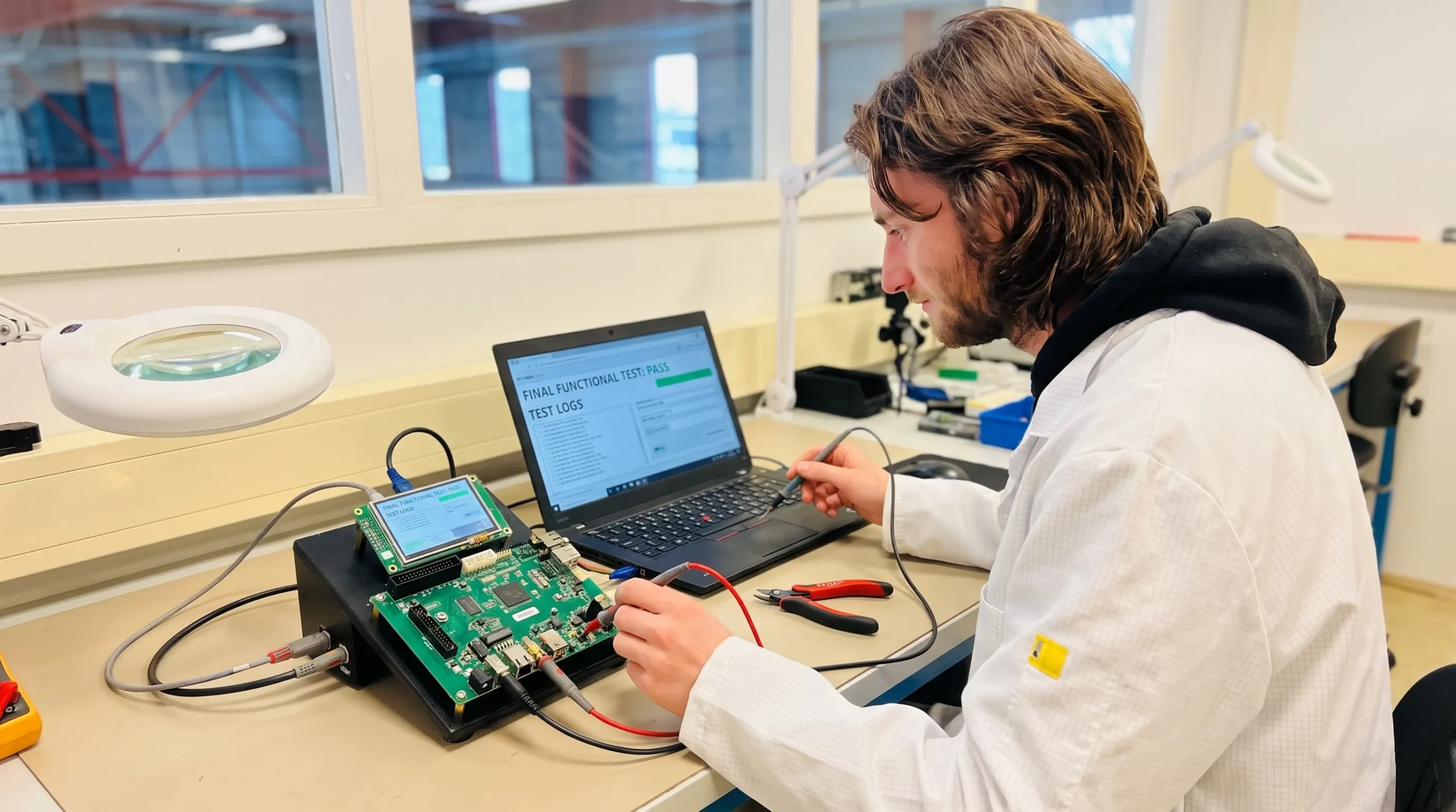
Prototype assembly is often optimised for learning. Volume assembly must be optimised for repeatability. The transition between the two is where many product launches slow down.
A prototype may be hand-modified, manually programmed or visually inspected by the development team. That can be acceptable for early validation, but it is not a production process. Before volume manufacturing, the assembly process must define how boards are built, tested, programmed, handled, repaired and released.
Teams should be cautious when a prototype works in the lab but lacks manufacturing evidence. Lab success does not automatically prove EMC robustness, thermal margin, assembly repeatability or field reliability. A production-ready product needs controlled documentation, test coverage, known process limits and a clear plan for managing changes.
ProMicro discusses this transition in more detail in its article on how an assembled circuit board becomes production-ready, including inspection, bring-up, testing and manufacturing readiness.
Common assembly-related risks to address early
Some assembly risks are visible immediately. Others only appear during certification, customer installation or months of field use. The earlier these risks are discussed, the easier they are to reduce.
Common warning signs include:
- The PCB layout is finished before test access and programming have been considered.
- The BOM contains parts without approved alternates or lifecycle review.
- Connectors, cables and enclosures are designed separately from the PCB assembly.
- Compliance assumptions are discussed only after prototypes are built.
- Functional testing checks only basic power-up instead of real operating modes.
- Firmware configuration is handled manually without clear traceability.
- Assembly feedback does not reach the design team in a structured way.
These issues do not mean a product is poorly engineered. They often appear because teams are under pressure, internal capacity is limited or responsibilities are split between too many suppliers. The solution is to treat assembly as part of product development rather than a final transaction.
Choosing an electronics assembly approach for complex products
For simple products, a transactional assembly supplier may be sufficient. For complex embedded products, power electronics, high-tech equipment or professional devices, assembly quality depends on engineering collaboration.
The right approach should connect design intent with manufacturing reality. That means reviewing component choices, PCB layout, enclosure constraints, test strategy, firmware loading, compliance risks and lifecycle expectations before production decisions are locked.
When evaluating an assembly and development partner, ask practical questions. How early can manufacturability be reviewed? Who owns test strategy? How are firmware revisions controlled? How are component substitutions assessed? How are assembly issues fed back into design improvements? How does the process support future production volumes?
The answers reveal whether the partner is simply building boards or helping create a reliable product.
Frequently asked questions
What is electronics assembly? Electronics assembly is the process of turning electronic designs, components, PCBs, firmware and mechanical parts into a finished or semi-finished product. It includes PCB assembly, inspection, testing, programming and often integration into an enclosure or larger system.
Why does electronics assembly affect product quality so strongly? Assembly is where design assumptions meet physical tolerances, soldering processes, component handling, firmware configuration and system integration. Weak assembly planning can lead to rework, inconsistent performance, certification delays or field failures.
Is PCB assembly the same as electronics assembly? PCB assembly is a major part of electronics assembly, but electronics assembly is broader. It may also include cables, connectors, heatsinks, enclosure integration, firmware loading, calibration, labelling, packaging and final functional testing.
When should assembly planning begin? Assembly planning should begin during product development, not after the design is released. Early planning helps improve manufacturability, testability, compliance readiness, component availability and long-term reliability.
How can companies reduce electronics assembly risks? Companies can reduce risk by defining requirements clearly, reviewing DFM and DFT early, controlling the BOM, planning test access, validating firmware loading, documenting revisions and using assembly feedback to improve the design.
Building quality into every assembly step
Electronics assembly is not a final hurdle at the end of development. It is a chain of engineering decisions that shape whether a product can be built, tested, certified, serviced and scaled with confidence.
For companies developing embedded systems, power electronics, connected products or high-value technical equipment, the most effective assembly strategy starts early. It connects requirements, hardware design, software, PCB layout, mechanical integration, compliance thinking and volume manufacturing preparation.
ProMicro supports organisations from first idea to volume-ready electronic solutions, combining embedded systems, power electronics, analogue electronics, PCB design, prototyping and manufacturing support. If your team needs additional engineering capacity or a partner who can help reduce hidden development risks, ProMicro can support the journey from concept to reliable product realisation.
