

Printed circuit board design is often treated as the stage where a schematic becomes a manufacturable layout. For professional electronic products, it is much more than that. The PCB determines how current returns, how switching energy is contained, how analogue and digital functions interact, how cables behave as antennas, and how consistently the product can be assembled at scale.
For engineering managers, CTOs, technical directors and product teams working in high-tech, machine manufacturing, robotics, automotive, defence or maritime markets, the stakes are high. A prototype that works on the bench can still fail during EMC testing, field operation or production ramp-up. The goal is not simply to route a board, but to create electronics that are electrically robust, mechanically practical, testable, compliant by design and ready for long-term use.
That is why printed circuit board design for EMC and manufacturability should be approached as a system engineering activity from the start.
Why EMC and manufacturability belong in the same design discussion
Electromagnetic compatibility and manufacturability are often discussed by different teams. EMC may sit with electronics engineers and compliance specialists, while manufacturability may be handled by PCB fabricators, assembly partners or production engineers. In practice, the two are tightly connected.
A layout choice that improves EMC can affect assembly cost, soldering reliability or inspection. A manufacturing choice, such as changing laminate, copper thickness, component package or stack-up, can affect impedance, thermal behaviour and noise coupling. If these topics are handled too late, the project can enter a cycle of re-spins, compliance delays and production compromises.
| PCB design decision | EMC impact | Manufacturability impact |
|---|---|---|
| Layer stack-up | Controls return paths, impedance and shielding effectiveness | Affects fabrication complexity, cost, yield and supplier availability |
| Component placement | Influences loop area, coupling and cable emissions | Affects assembly access, thermal profiles, rework and inspection |
| Ground and power planes | Reduces noise and provides stable references when designed correctly | Requires clear fabrication rules, via strategy and copper balance |
| Connector position | Determines cable coupling and enclosure bonding strategy | Affects enclosure design, assembly sequence and serviceability |
| Component package choice | Influences parasitics, switching behaviour and thermal performance | Affects availability, solderability, inspection and lifecycle support |
| Test access | Helps diagnose EMC, power and signal issues early | Enables production testing, programming and fault isolation |
The practical lesson is clear: EMC is not a final test activity, and manufacturability is not only the responsibility of the factory. Both must influence architecture, schematic design, PCB layout, enclosure integration and verification planning.
Start with the product context, not the board outline
A strong PCB layout begins before the first component is placed. The team needs to understand the product environment, the electrical architecture and the compliance route. A board for a battery-powered sensor node has different risks from a motor drive in a machine, a maritime control unit, a wireless automotive accessory or a defence-related embedded system.
Important context includes operating voltage, current levels, switching frequencies, cable lengths, enclosure material, grounding concept, environmental stress, thermal constraints, expected production volume and maintenance requirements. The application environment matters just as much as the schematic. Long external cables, inductive loads, motors, relays, high-speed communication links and wireless radios all create EMC-sensitive interfaces.
This is also the right time to identify applicable standards and market requirements. For EU products, this may include EMC, RED, CE-related requirements, safety standards or sector-specific obligations depending on the product category. If your team is still defining the subject, ProMicro’s overview of what EMC means and when to take it into account is a useful starting point.
The earlier these constraints are translated into design rules, the more freedom the team has to avoid problems. Late EMC fixes often involve ferrites, shielding, filters or layout changes that are more expensive than a well-planned architecture.
Stack-up, grounding and return paths
The stack-up is one of the most important decisions in EMC-conscious PCB design. It defines reference planes, power distribution, impedance control, interlayer coupling and the physical return paths for currents. A two-layer board may be suitable for simple, low-risk products, but complex embedded systems, mixed-signal electronics, motor drives or wireless products often benefit from four or more layers.
A continuous reference plane helps signals return close to their outgoing path, reducing loop area and radiated emissions. Breaks in the return path, poorly planned plane splits and long detours can create noise, crosstalk and unpredictable behaviour. This is especially important for fast digital edges, switching regulators, clock lines and communication interfaces.
Grounding should be designed around current flow, not around labels on the schematic. Analogue ground, digital ground, power ground and chassis ground can be useful concepts, but they can also create problems if split without a clear return strategy. In many cases, a well-controlled common reference with careful placement and current separation performs better than arbitrary ground islands.
Power distribution requires the same attention. Decoupling capacitors must be placed close to the pins they serve, with short connections to the relevant power and ground planes. Bulk capacitance, local high-frequency decoupling and regulator stability should be considered together. For motor drives, DC/DC converters and high-current loads, the layout of switching loops is critical. Small loop area, short paths and appropriate copper geometry reduce both emissions and thermal stress.
Component placement as an EMC and production decision
Component placement is the bridge between the schematic and the physical product. It determines whether the PCB layout can achieve clean return paths, short noise-sensitive connections and practical assembly.
A good placement strategy groups functions according to energy and sensitivity. Power entry, protection, filtering and conversion should have a clear flow. High-current and high dv/dt areas should be compact and kept away from sensitive analogue circuitry, sensor inputs and radio sections. Clocks, crystals and oscillators should be placed close to the devices they serve, with short traces and controlled references.
Connectors deserve special attention. They are often the point where internal PCB noise becomes system-level EMC behaviour, especially when cables leave the enclosure. Connector placement should align with filtering, ESD protection, chassis bonding and mechanical integration. If filters are required, they should usually be placed close to the entry or exit point rather than deep inside the board.
Manufacturability also depends on placement. Components need suitable spacing for pick-and-place, soldering, automated optical inspection, thermal profiling and rework. Tall components, heat-generating devices, fine-pitch packages and connectors should be reviewed in relation to assembly sequence and enclosure constraints. A board that is electrically elegant but difficult to assemble repeatedly is not production-ready.
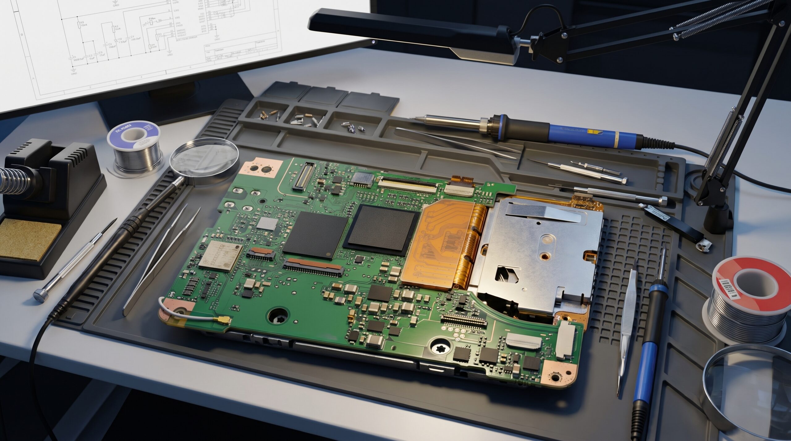
Routing practices that reduce EMC risk
Routing is where many EMC issues become embedded into the product. The most important rule is to think in loops, not just traces. Every signal has a return current. Every switching path has a loop area. Every high-speed edge can couple into nearby structures if the return path is interrupted or poorly controlled.
High-speed digital signals should maintain a continuous reference plane and avoid unnecessary layer changes. If a signal changes layers, the return path must also be supported, often through nearby stitching vias or appropriate plane continuity. Differential pairs need controlled spacing and impedance where required, but they also need a sound reference environment. Pair matching alone does not compensate for poor return paths or bad connector transitions.
Switching regulator layouts require particular discipline. The hot loop should be as small as possible, high-current paths should be short and wide enough for current and thermal needs, and sensitive feedback nodes should be protected from noisy switching nodes. Copper pours can help with heat spreading and impedance, but only if they are connected intentionally and do not create unintended coupling structures.
For mixed-signal designs, keep analogue inputs away from noisy power and digital areas. Guarding, filtering and shielding may help, but the best results usually come from correct placement, reference planning and signal flow. Sensor interfaces, low-level measurements and precision analogue circuits should be treated as system-level risks, not merely schematic blocks.
These layout choices should also be reviewed in the context of embedded architecture. Firmware timing, processor clocking, communication protocols and power states can all influence EMC behaviour. ProMicro has discussed this wider relationship in its guide to embedded design decisions that affect EMC, safety and lifecycle.
Designing for manufacturing without weakening EMC
Design for manufacturability is not about making the board cheaper at any cost. It is about making the board repeatable, inspectable, testable and suitable for the intended production volume. The challenge is to achieve this without compromising electrical performance.
Land patterns should follow component manufacturer guidance and assembly partner capabilities. Fine-pitch devices, BGAs, QFNs and high-current terminals need particular attention to solder paste, via-in-pad, stencil design and inspection strategy. If changes are made by the assembly partner, the electronics team should understand whether those changes affect thermal paths, parasitics or EMC-sensitive connections.
PCB fabrication choices also matter. Laminate selection, copper thickness, solder mask, via technology, controlled impedance requirements and panelisation can all affect product quality. For high-current power electronics, copper weight and thermal reliefs must be designed with both assembly and electrical performance in mind. For RF or high-speed designs, material tolerances and stack-up control become more important.
If your project is approaching supplier selection or production preparation, ProMicro’s article on PCB fabrication and assembly choices that affect product quality explores these decisions in more detail.
A practical DFM review should include solderability, component orientation, placement clearances, fiducials, tooling holes, panel break-off strategy, test point access, programming access and inspection feasibility. It should also consider component availability and lifecycle risk. A technically correct design built around difficult-to-source components may create avoidable production and maintenance problems later.
Prototype planning and EMC pre-compliance
A first prototype should be designed to learn, not only to demonstrate functionality. That means including measurement points, current sense options, programming access, diagnostic interfaces and provisions for alternative component values where the risk is high. For example, filter footprints can be designed to support several configurations, provided they are not used as a substitute for good layout.
Pre-compliance testing is valuable because it identifies problems while the design can still be changed. Near-field probing, conducted emission measurements, ESD checks and basic immunity investigations can reveal coupling paths and weak points before formal testing. These activities do not guarantee certification, but they help reduce uncertainty and focus engineering effort.
A prototype should also be reviewed for production assumptions. Can the board be assembled with the intended process? Are parts available in production quantities? Are there soldering or inspection risks? Does the enclosure affect grounding or cable emissions? Are thermal margins realistic outside the lab? These questions help prevent the common situation where a prototype functions correctly but cannot be scaled without redesign.
Documentation and compliance evidence
A manufacturable PCB is not complete without documentation. The release package should allow a manufacturer, assembler and test team to build the same product repeatedly. It should also support traceability if a fault, component change or compliance question appears later.
Typical documentation includes schematic files, PCB data, Gerber or ODB++ output, drill files, bill of materials, approved manufacturer list, pick-and-place files, assembly drawings, test instructions, firmware programming notes and revision history. For regulated or safety-relevant products, design rationale and verification records may also be needed.
In automotive programmes, this wider compliance mindset is especially familiar because engineering validation, vehicle integration evidence and market-entry documentation may all have to align. Services that provide official vehicle Certificates of Conformity illustrate how formal conformity documents can sit alongside technical validation in the broader product and vehicle compliance landscape.
For electronics teams, the key point is that compliance confidence is built through evidence. Layout reviews, design calculations, material choices, test results and change control all contribute. A PCB that passes a single test once, but lacks controlled documentation, is not yet a robust production design.
Common PCB design traps that lead to late rework
Many EMC and manufacturability issues are avoidable if they are challenged early. The following traps appear repeatedly in complex electronic product development:
- Treating EMC as a test-lab problem instead of an architecture and layout problem.
- Routing fast signals across plane gaps or through poorly controlled return paths.
- Placing filters too far from connectors or cable entry points.
- Selecting component packages without checking assembly, inspection and lifecycle implications.
- Leaving programming, test and diagnostic access until after the first prototype.
- Designing the PCB independently from the enclosure, cable harness and grounding concept.
- Assuming that a working prototype is automatically ready for volume production.
The cost of correcting these issues rises as the project moves from concept to prototype, from prototype to certification, and from certification to production. Early technical reviews are usually much more efficient than late corrective actions.
A practical review checklist
Before releasing a PCB design for prototype build or production preparation, review it from three perspectives: electrical behaviour, manufacturing repeatability and lifecycle support.
| Review area | Questions to ask before release |
|---|---|
| EMC architecture | Are noisy and sensitive functions separated? Are return paths continuous? Are cable interfaces protected and filtered correctly? |
| Power integrity | Are regulator loops compact? Is decoupling placed effectively? Are current paths and thermal paths suitable? |
| Layout quality | Are impedance, spacing, creepage, clearance and routing rules aligned with the application? |
| Manufacturing readiness | Are land patterns, clearances, fiducials, panelisation and inspection access suitable for the assembly process? |
| Test readiness | Are there accessible test points, programming options and diagnostics for prototype and production testing? |
| Documentation | Are BOM, assembly data, drawings, revisions and manufacturing notes complete and controlled? |
| Lifecycle | Are critical components available, replaceable if needed and suitable for long-term support? |
This review should not be a paperwork exercise. It should involve the people responsible for hardware, embedded software, mechanical integration, manufacturing and product ownership. Many hidden risks only appear when these disciplines are considered together.
For teams preparing a design for both early validation and later scaling, ProMicro’s guide on how to prepare a PCB design for prototyping and volume build provides a useful companion to this EMC and manufacturability perspective.
Frequently asked questions
How early should EMC be considered in printed circuit board design? EMC should be considered before the schematic and layout are finalised. Architecture, power distribution, grounding, component placement, cable interfaces and enclosure design all influence EMC. Waiting until formal testing usually increases the risk of expensive redesign.
Does a four-layer PCB automatically improve EMC? Not automatically. A four-layer board can improve EMC when it provides continuous reference planes, controlled return paths and better power distribution. If the stack-up, routing or grounding concept is poor, adding layers alone will not solve the problem.
What is the difference between DFM and DFA in PCB development? DFM, or design for manufacturability, focuses on whether the PCB can be fabricated reliably. DFA, or design for assembly, focuses on whether components can be placed, soldered, inspected and reworked consistently. Both are needed for production-ready electronics.
Can EMC problems be fixed after the prototype is built? Some EMC issues can be improved after prototype testing with filtering, shielding or layout adjustments. However, root causes such as poor return paths, bad component placement or unsuitable stack-up often require PCB redesign. Early EMC-aware design is usually more effective.
What should be included in a manufacturing-ready PCB release package? A release package should normally include schematic data, PCB manufacturing files, BOM, approved alternatives, pick-and-place data, assembly drawings, test instructions, programming notes and revision control. The exact package depends on product complexity and manufacturing process.
Build EMC-aware, manufacturable electronics with ProMicro
Reliable electronics require more than a correctly routed board. They require system-level thinking across embedded hardware, power electronics, analogue design, firmware behaviour, enclosure integration, compliance preparation, prototyping and production support.
ProMicro supports companies developing complex electronic products from first idea through to volume solutions. If your internal team needs extra specialist capacity, EMC-aware PCB design expertise or a partner who can identify hidden technical risks early, ProMicro can help turn complex product requirements into robust, scalable electronics.
