
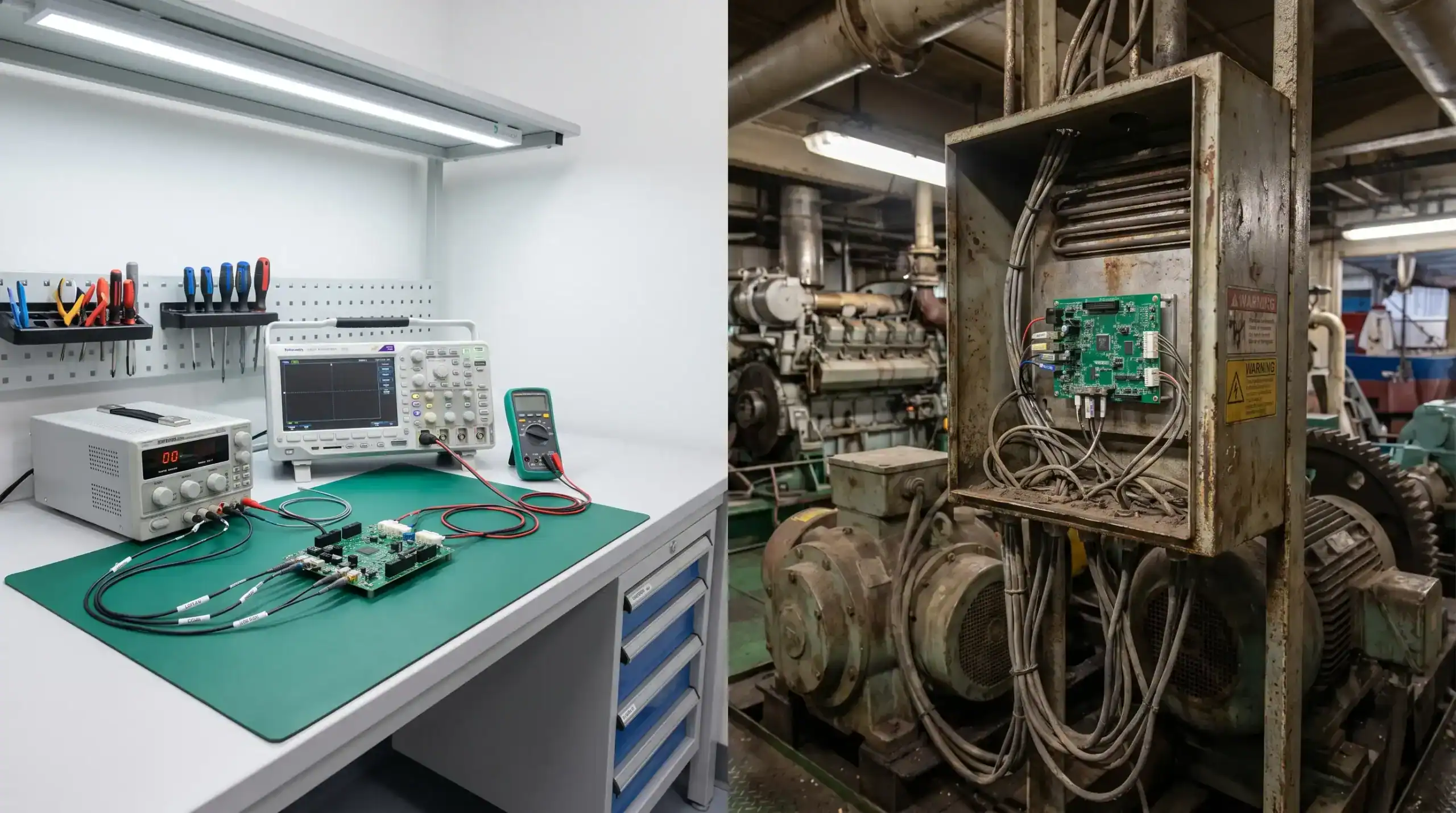
Circuit board manufacturing risk is rarely created at the factory gate. In many complex electronics projects, the most expensive problems are introduced much earlier, during requirements capture, architecture decisions, component selection, PCB layout and prototype planning.
For OEMs in defence, maritime, robotics, machine manufacturing, automotive, high-tech and professional consumer electronics, a circuit board is not just an interconnection platform. It is part of a complete product system that must survive real operating conditions, interact safely with power and software, pass compliance testing, and remain manufacturable for years.
Addressing these risks early does not mean slowing development down. It means making the right engineering decisions before they become locked into the design, supply chain or certification route.
Why circuit board manufacturing risk starts before manufacturing
Manufacturing partners can only build what the design package enables them to build. If the board stack-up is marginal, if thermal paths are underestimated, if components are hard to source, or if the test strategy is missing, the assembler may still produce a batch. The problem is that yield, reliability and compliance may be unpredictable.
This is why circuit board manufacturing should be considered during system definition, not after schematic completion. The product context shapes almost every board-level decision: available enclosure space, cooling, vibration, input power quality, electromagnetic environment, service life, cleaning processes, firmware update strategy, and expected production volume.
A prototype that works on the bench can still fail when exposed to conducted disturbances, salt air, motor drive noise, thermal cycling, mechanical shock or production variation. Early reviews help identify which assumptions are safe, which need testing, and which should be redesigned before release.
Risk 1: unclear operating requirements
A PCB cannot be designed reliably if the product environment is only described in general terms. Terms such as industrial, outdoor, marine, rugged or automotive-like are useful starting points, but they are not enough for engineering decisions.
The design team needs to understand the real use case. Will the electronics sit near a motor, solenoid, compressor or high-current actuator? Will users connect external cables in the field? Is the product expected to tolerate reverse polarity, load dumps, ESD, condensation, vibration or poor grounding? Does the enclosure trap heat? Will the board be repaired, replaced or sealed for life?
These questions affect creepage and clearance, connector choice, coating strategy, PCB material, copper thickness, grounding, filtering, fusing, diagnostics and test coverage. Missing this information early often leads to late redesign, especially when prototypes move from a controlled lab to an actual machine, vessel, vehicle or customer site.
Risk 2: manufacturability treated as a layout clean-up task
Design for manufacturability is not just a final checklist before Gerber export. It influences the board from the moment the architecture is split into functional blocks. Layer count, stack-up, impedance control, via types, copper weight, minimum track widths, component placement, thermal reliefs and panelisation all affect whether a board can be built repeatedly and inspected efficiently.
A common issue is designing to the absolute limit of a fabrication capability without a strong reason. Very fine features, tight tolerances, unusual materials or complex via structures may be justified for compact, high-speed or power-dense products. But each choice should be deliberate, documented and aligned with the expected production volume.
For a deeper view of how fabrication and assembly decisions influence reliability, ProMicro has also covered PCB fab and assembly choices that affect product quality. The key point is that manufacturing quality is not only determined by supplier skill. It is also determined by how much margin the design gives the supplier.
| Early risk area | Question to ask before layout release | Typical consequence if ignored |
|---|---|---|
| Stack-up | Is the layer structure suitable for EMC, impedance, power and manufacturability? | Late layout changes, EMC issues or inconsistent performance |
| Component placement | Can parts be assembled, inspected, reworked and cooled? | Low yield, rework cost or thermal stress |
| Copper and spacing | Are current, voltage, creepage and thermal requirements understood? | Safety risks, overheating or field failures |
| Mechanical constraints | Is the PCB aligned with enclosure, connectors, mounting and service access? | Mechanical interference or expensive tooling changes |
| Test access | Can the board be programmed, measured and functionally tested in production? | Slow debugging, poor traceability or hidden defects |

Risk 3: component choices made without lifecycle thinking
Component selection is one of the most underestimated circuit board manufacturing risks. A component may be electrically suitable, easy to obtain for prototypes and still be a poor choice for volume production or long-term support.
Engineering teams should review availability, package options, second-source potential, temperature grade, derating, documentation quality, manufacturer roadmap and expected product lifetime. In professional markets, the cost of redesigning around an unavailable component can be far higher than the cost difference between two parts at the start.
This risk is especially relevant for embedded systems that combine microcontrollers, power conversion, wireless modules, sensors and analogue front ends. A certified wireless module, for example, can simplify part of the compliance path, but it does not remove the need for careful antenna placement, grounding, power supply quality and enclosure integration.
Component lifecycle decisions should also be reflected in the bill of materials. Approved alternates, manufacturer part numbers, package constraints and substitution rules need to be clear. If the purchasing team or assembly partner has to guess, production risk increases.
Risk 4: power and thermal behaviour underestimated
Power electronics and dense embedded boards often fail because thermal and power integrity were treated too late. A circuit can operate correctly for a short bench test, but degrade under continuous load, high ambient temperature, enclosed mounting or worst-case input voltage.
Early thermal thinking should include losses in switching devices, regulators, current sense elements, connectors, fuses, magnetics and PCB copper. Copper pours can help, but they are not a complete thermal strategy by themselves. The board, enclosure, airflow, mounting points and duty cycle all contribute to the final temperature profile.
Power integrity is equally important. Fast switching edges, motor drives, wireless bursts and digital processors can create disturbances that affect sensors, analogue measurements, communication interfaces and firmware behaviour. If return paths, decoupling, current loops and grounding are not considered early, the board may require major layout changes after testing.
This is where an integrated hardware and embedded systems view matters. The safest design is not always the one with the most filtering or the largest safety margin everywhere. It is the one where electrical behaviour, software control, diagnostics, mechanical integration and manufacturing constraints have been considered together.
Risk 5: EMC, RED and CE considerations left until the test lab
Compliance should not be treated as a final administrative step. For products placed on the European market, CE marking is linked to applicable safety, EMC and radio requirements, depending on the product type. The European Commission provides general guidance on CE marking requirements, but engineering teams still need to translate those requirements into practical design decisions.
EMC performance is strongly influenced by PCB layout. Return current paths, cable exits, shield connections, switching loops, clock routing, connector placement and filtering topology can determine whether the product behaves well in conducted and radiated tests. A late ferrite or enclosure change may help, but it is not a substitute for designing the board and system with EMC in mind.
Wireless products add further risk because radio performance, antenna integration, firmware behaviour and mechanical design all interact. If RED-related requirements are considered only after the PCB is complete, the project may face unexpected retesting, antenna changes or enclosure constraints.
ProMicro has discussed related system-level issues in embedded system design mistakes that delay certification. The same principle applies to circuit board manufacturing: compliance risk is reduced when design intent, physical layout and test evidence develop together.
Risk 6: production test strategy added after prototypes work
A working prototype answers one question: can the concept function under the tested conditions? It does not prove that the product can be built repeatedly, inspected efficiently or released safely to customers.
Production test strategy should be defined before the board is finalised. The team should know how the PCB will be programmed, how critical rails will be measured, how sensors will be calibrated, how communication interfaces will be verified, and which failures must be detected before shipment.
Test access can be difficult to add later, especially in compact products. Missing test pads, inaccessible connectors, unclear firmware modes or no calibration routine can slow every production batch. In regulated or high-value applications, the lack of traceable test data can also create liability and service challenges.
The test strategy does not need to make every board expensive to validate. It needs to match the product risk. A simple control board may need basic functional verification, while a safety-related power or communication system may require more detailed logging, boundary checks and environmental testing.
Risk 7: mechanical and enclosure integration considered separately
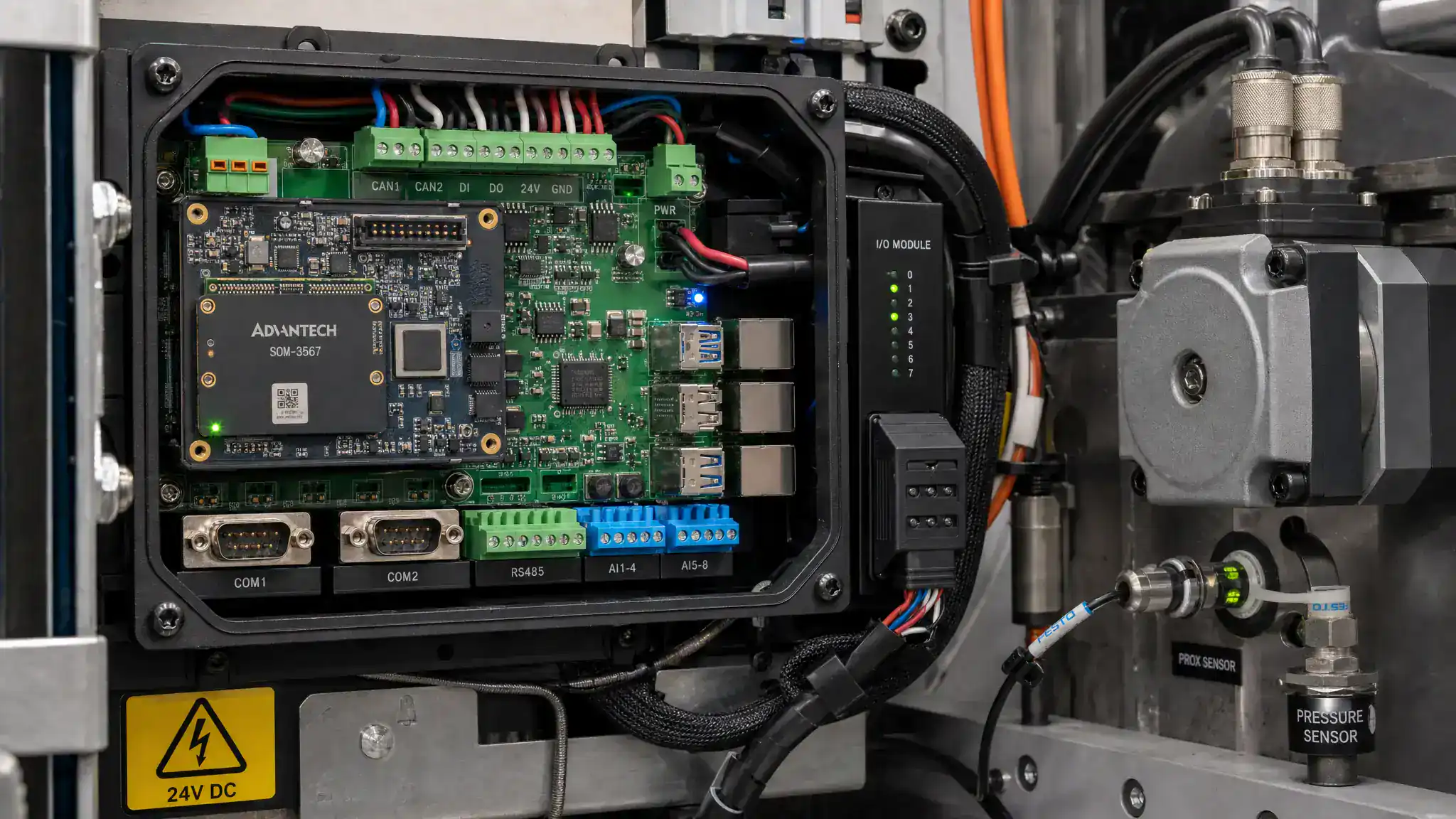
Many board manufacturing problems are actually system integration problems. The PCB may be electrically correct, but still difficult to assemble, cool, seal, connect or service.
Connector orientation, mounting hole tolerance, cable strain relief, enclosure wall thickness, gasket compression, display alignment, antenna clearance and heat transfer paths all influence board design. If mechanical and electronic design run in isolation, issues often appear late, when enclosure tooling, cable harnesses or production fixtures are already planned.
This is particularly relevant for maritime, robotics, machine building and automotive-adjacent products, where vibration, moisture, operator handling and installation variation are part of real life. A robust circuit board design should fit the product mechanically as well as electrically.
Risk 8: manufacturing data and revision control are incomplete
Even a well-designed board can create manufacturing delays if the data package is incomplete. Fabricators and assemblers need clear, controlled and consistent information. This includes fabrication files, assembly drawings, pick-and-place data, bill of materials, approved alternates, polarity markings, firmware versions, test instructions and revision history.
Ambiguity causes questions, delays and sometimes incorrect assumptions. A footprint that does not match the component, a missing polarity note, an unclear solder paste requirement or an outdated BOM can turn into rework or scrap.
Acceptance criteria should also be agreed in advance. Many organisations use IPC standards as a common language for PCB and assembly quality, and the IPC standards library is widely referenced across the electronics industry. The relevant class, workmanship expectations and inspection requirements should match the product risk and market.
Risk 9: supplier capability not matched to product risk
The right manufacturing partner for a simple prototype is not always the right partner for a complex, long-life OEM product. Supplier selection should consider technical fit, quality systems, engineering support, traceability, process capability, communication quality and willingness to support scaling from prototype to volume.
For high-value products, it is often useful to assess whether the manufacturer can support DFM feedback, controlled substitutions, inspection planning, test fixture integration and repeatable documentation. ProMicro’s guide on how to assess printed circuit board manufacturers explores this decision in more detail.
Commercial timing also matters. In connected fitness, sports-tech or professional consumer electronics, demand generation may be planned months before production stabilises. If a brand is working with a specialist growth partner such as sports marketing agency OPTYO, the manufacturing plan needs the same discipline as the go-to-market plan. Otherwise, marketing momentum can expose supply, quality or reliability weaknesses faster than the engineering team can correct them.
A practical early-risk review framework
Circuit board manufacturing risk is easiest to reduce when reviews are tied to design maturity. The aim is not to create bureaucracy, but to ensure that important decisions are made with the right information.
| Review moment | Main focus | Evidence to collect |
|---|---|---|
| Concept and architecture | Product context, environment, compliance route and system partitioning | Requirement assumptions, risk register, initial block diagram |
| Schematic review | Component lifecycle, power architecture, protection, sensing and test access | Preliminary BOM, derating notes, interface definitions |
| Layout review | Stack-up, EMC, thermal paths, DFM, mechanical fit and assembly access | PCB rules, 3D checks, design rule reports, layout review notes |
| Prototype build | Bring-up plan, measurement points, firmware loading and fault logging | Test plan, inspection notes, issue tracker |
| Pre-production | Yield, documentation, acceptance criteria, supplier readiness and traceability | Controlled data pack, test records, revision release package |
A useful review also separates assumptions from verified facts. For example, there is a major difference between assuming a board will pass EMC because a reference design was used and having measured emissions in a representative enclosure with production-like cables. The earlier this distinction is made, the easier it is to plan realistic tests and design margins.
How ProMicro helps reduce early manufacturing risk
ProMicro supports electronic product development from first idea through to volume solutions, with expertise in embedded systems, power electronics, analogue electronics, PCB design, system engineering, enclosure design, rapid prototyping and manufacturing preparation.
That combination is important because circuit board manufacturing risks rarely sit in one discipline. A thermal issue may involve PCB copper, firmware duty cycle and enclosure design. An EMC problem may involve layout, cable routing, power conversion and software states. A supply chain issue may affect firmware, test fixtures and certification evidence.
By reviewing explicit requirements and hidden real-world constraints early, ProMicro helps engineering teams make design choices that are more robust, testable, manufacturable and maintainable. For companies with limited internal capacity or specialist expertise, this can reduce late-stage rework and create a clearer route from concept to production-ready electronics.
Frequently asked questions
When should circuit board manufacturing risks be reviewed? They should be reviewed from the concept and architecture stage, then again at schematic, layout, prototype and pre-production stages. Waiting until files are sent to a manufacturer often leaves too little room for efficient changes.
Is a working prototype enough to start volume manufacturing? No. A prototype proves limited functionality under specific conditions. Volume manufacturing also requires controlled documentation, test strategy, supplier readiness, component availability, inspection criteria and evidence that the product behaves reliably in its intended environment.
Which circuit board manufacturing risks are most often underestimated? Commonly underestimated risks include EMC behaviour, thermal performance, component lifecycle, production test access, enclosure integration and unclear manufacturing data. These risks often remain hidden until certification, pilot builds or field use.
How does PCB layout affect compliance? Layout affects return paths, switching loops, grounding, cable coupling, antenna performance, creepage, clearance and filtering effectiveness. These factors can influence EMC, RED and safety-related outcomes, depending on the product and market.
Can early risk reviews reduce development time? Yes, when they prevent late redesign. Early reviews may add focused engineering effort at the start, but they often reduce delays caused by failed tests, rework, unavailable components or manufacturing questions.
Build circuit boards with the full product lifecycle in mind
Circuit board manufacturing is not only about producing a PCB. It is about creating electronics that can be built, tested, certified, maintained and supported in real operating conditions.
If your team is developing a complex electronic product and wants to reduce manufacturing, compliance or lifecycle risk early, ProMicro can support the journey from concept and prototype to production-ready electronics.
