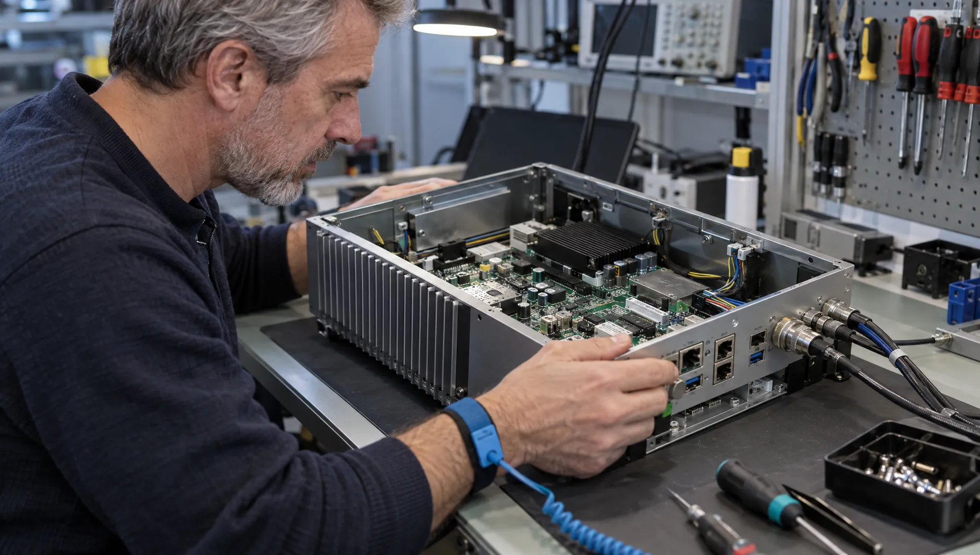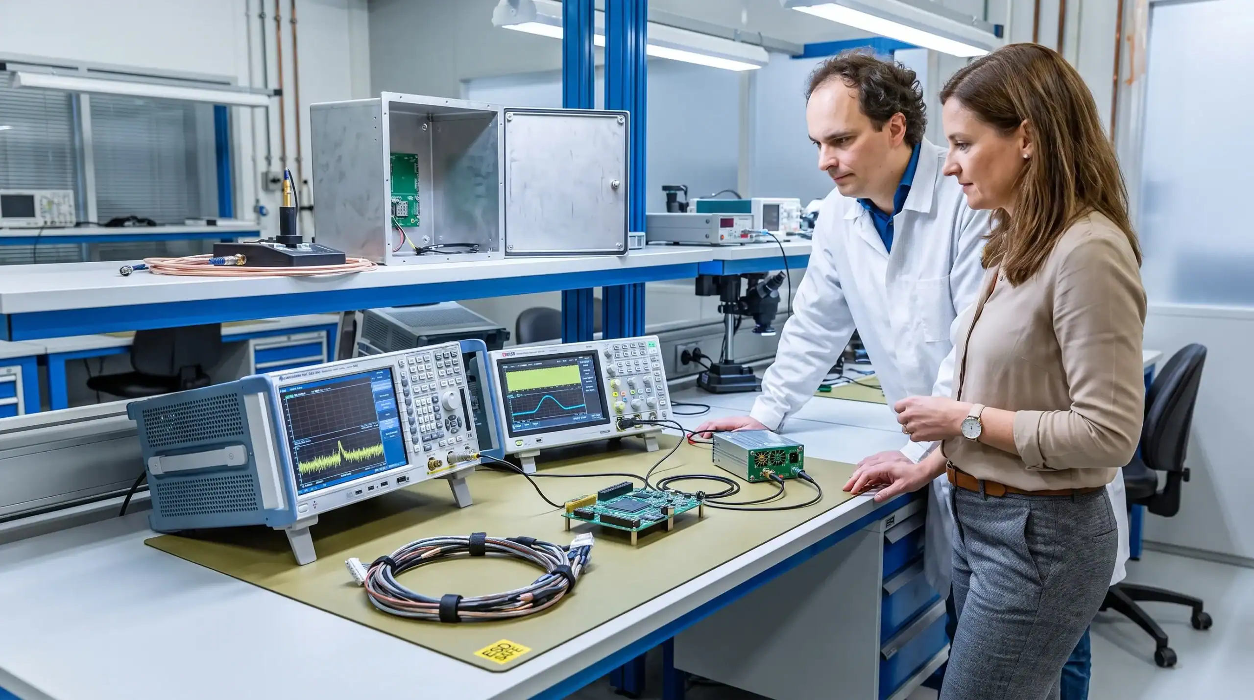
Electromagnetic compatibility testing should be planned long before a product is sent to a certification lab. For technical teams developing embedded systems, power electronics, motor drives, sensors or connected equipment, EMC is not a final inspection step. It is a design constraint that affects architecture, PCB layout, enclosure choices, cabling, firmware modes and the evidence needed for CE or market approval.
The practical objective is simple: arrive at formal testing with a product configuration that is representative, stable and already understood. That does not guarantee a pass, but it reduces the risk of discovering fundamental design issues when the project has little time or budget left.
Why planning before the lab protects certification
Late EMC failures are rarely isolated events. A radiated emissions issue may point to a power converter, a cable shield, a grounding strategy or a firmware state that was never tested under realistic load. Correcting it after mechanical tooling, supplier selection or production planning has started can affect the enclosure, PCB, bill of materials and software release process.
For defence, maritime, robotics, machine manufacturing and high-tech products, the cost is not only the extra lab day. Delays can push back customer acceptance, field trials, safety validation and market launch. Planning turns EMC from a reactive lab problem into an engineering workflow.
| Activity | Purpose | Best timing |
|---|---|---|
| EMC risk assessment | Identify likely emission and immunity risks | Concept and architecture phase |
| Pre-compliance checks | Find issues before formal lab time | Prototype and design iteration phase |
| Formal certification test | Produce test evidence for the selected market route | After design freeze and configuration control |
Turning product context into electromagnetic compatibility testing requirements
Before booking lab time, translate the product context into test requirements. The relevant route depends on where the product will be sold, what it does and how it connects to other equipment. In Europe, CE marking may involve the EMC Directive, the Radio Equipment Directive for wireless products, the Low Voltage Directive, machinery-related requirements or sector-specific standards.
The important engineering task is to avoid treating standards as a checklist found at the end of the project. Standards have to be interpreted against intended use, installation environment, ports, cables, user access, enclosure concept and operating modes.
Standards, directives and intended use
A product with wireless communication, motor control and external cables may need a different test plan from a battery-powered embedded controller with no radio and short internal wiring. An electromagnetic compatibility testing plan should therefore define the applicable standards, the test levels, the product configuration and the rationale behind those choices.
When the applicable standard is not obvious, document the assumptions early. That record helps engineering managers, certification bodies and external labs understand why a given test route was selected.
Real operating environment, not only the lab setup
The lab setup must represent the real electromagnetic environment as closely as possible. A machine controller installed next to inverters, contactors and long motor cables faces different risks from a medical device used near radio transmitters or a maritime product exposed to long cable runs and harsh grounding conditions.
| Application context | Typical EMC concerns | Planning implication |
|---|---|---|
| Industrial machine control | Fast switching loads, contactors and long cables | Define representative cable lengths and operating cycles |
| Robotics and motor drives | PWM switching, encoders and sensor feedback | Test noisy and sensitive subsystems together |
| Maritime electronics | Grounding variation, corrosion risks and long harnesses | Review bonding, shielding and installation assumptions |
| Defence and high-tech equipment | Dense electronics and strict reliability expectations | Include margins, configuration control and early risk reviews |
| Wireless or IoT products | Radio coexistence and intentional transmitters | Align EMC planning with radio and antenna design |
Build EMC thinking into architecture before hardware freezes
By the time electromagnetic compatibility testing is booked, many decisions are already hard to change. Partitioning noisy and sensitive circuits, selecting power topology, defining reference planes, choosing connectors and allocating enclosure space for filters all influence the eventual test result.
Good EMC planning is therefore connected to system architecture. Motor drivers, DC-DC converters, analogue front ends, sensors, displays, radio modules and external ports should not be designed as separate islands. Their interaction is where many practical EMC risks appear. ProMicro covers these issues in more depth in its guide to EMC design principles for reliable electronics in demanding environments.
Firmware also matters. A product may pass in an idle state and fail when all outputs switch, a radio transmits, a display refreshes or a motor accelerates. Test modes should be specified before the lab visit so the product can be exercised repeatably during emissions and immunity tests.
Plan pre-compliance before the certification campaign
Formal lab testing is not the best place to debug unknown behaviour. The schedule is limited, the setup is controlled and every design change can create a retest question. Pre-compliance work gives the team a safer place to learn how the product behaves.
A sensible electromagnetic compatibility testing strategy usually includes design reviews, bench measurements and targeted pre-compliance scans before the certification campaign. The equipment does not always need to replicate a full accredited lab, but the method must be disciplined enough to identify trends, compare design changes and focus attention on the highest risk areas.
| Planning stage | What to check | Useful output |
|---|---|---|
| Schematic and layout review | Filters, return paths, isolation, clocking and protection | List of design risks before prototype release |
| Baseline emissions scan | Conducted and radiated behaviour under key modes | Frequency ranges and operating states of concern |
| Immunity-oriented checks | Resets, communication errors and analogue drift | Weak points in grounding, shielding or firmware recovery |
| Corrective iteration | Component changes, layout changes or enclosure changes | Evidence that changes improved the result |
| Lab readiness review | Configuration, accessories, firmware and documentation | Stable test package for the certification lab |

Define the test configuration before you define the test date
One common weakness in electromagnetic compatibility testing is an unstable or under-specified configuration. If the firmware, cable set, enclosure, power supply or product variant changes during the test campaign, results become harder to interpret and may no longer represent the product that will be shipped.
Configuration control does not need to be bureaucratic, but it does need to be explicit. The test team should know which hardware revision is being tested, which firmware version is installed, what loads are connected and which accessories are representative of real use.
Key items to define before lab booking include:
- Product hardware revision, PCB revision and bill of materials status
- Firmware version, test modes and communication settings
- Power supply type, input range and grounding arrangement
- Cable types, cable lengths, shielding and connector configuration
- External loads, sensors, actuators and representative peripherals
- Worst-case product variant when several models share the same platform
- Photos, setup drawings and operating instructions for repeatability
This preparation also helps when a lab asks how the product should be monitored during immunity tests. For example, a simple pass or fail indicator may not be enough if the real risk is measurement drift, communication degradation or a safety-related reset.
Treat PCB, enclosure and cabling as one EMC system
A good electromagnetic compatibility testing plan does not treat the PCB as the whole product. The enclosure, cable exits, connector placement, shield terminations, grounding method and mechanical constraints all affect emissions and immunity.
This is especially relevant for products that combine power electronics, analogue measurement and embedded processing. A clean schematic can still perform poorly if return currents are forced through sensitive areas, if high di/dt loops are large or if cable shields terminate in a way that injects noise into the wrong reference. The connection between layout and compliance is explained further in ProMicro’s article on how PCB board design affects reliability and EMC.
Enclosure design should also be reviewed before certification. Plastic housings, metal panels, gaskets, cable glands and connector cut-outs can change the radiating structure of the product. If EMC filters are expected to solve problems, they need space, thermal consideration and a defined connection to the reference structure.
Plan what happens if a test fails
The value of early electromagnetic compatibility testing is not only in confirming readiness. It also creates a controlled way to respond when the product behaves unexpectedly. A failed test should trigger a clear engineering process, not a rushed sequence of unrecorded lab modifications.
Before formal testing, decide who can approve design changes, how changes will be documented and which measurements must be repeated after a modification. A ferrite added during a lab session, for example, may help identify a noise path, but it is not automatically a production-ready solution. The final fix may need component qualification, mechanical review, thermal review, cost review and lifecycle assessment.
This is where product development discipline matters. EMC corrections can interact with safety, maintainability, firmware behaviour and manufacturing repeatability. Treating failures as engineering data helps teams protect the wider product instead of optimising only for one lab result.
A practical planning timeline for certification-aware development
For complex electronics, electromagnetic compatibility testing fits best as a thread through the project rather than a single milestone at the end. The timeline below is a practical way to connect EMC planning to product maturity.
| Development phase | EMC planning focus | Decision to make |
|---|---|---|
| Concept | Intended use, markets and operating environment | Which regulatory route and risk profile apply? |
| Architecture | Power, grounding, interfaces and enclosure concept | Where are the likely emission and immunity risks? |
| Detailed design | PCB layout, filtering, shielding and firmware modes | Are mitigation measures designed in rather than added later? |
| Prototype | Bench checks and pre-compliance measurements | Which issues need correction before design freeze? |
| Design freeze | Configuration control and lab documentation | Is the test sample representative of production intent? |
| Certification campaign | Formal testing and controlled issue resolution | Are changes recorded and assessed for production impact? |
This timeline is particularly useful when internal teams are under capacity pressure. It gives technical directors and engineering managers a way to keep EMC visible without slowing every design decision down.
How ProMicro approaches EMC planning in electronic product development
When electromagnetic compatibility testing is treated as part of system engineering, teams can make better decisions earlier. ProMicro supports technically demanding electronics development across embedded systems, power electronics, analogue electronics, PCB design, prototyping and preparation for volume manufacturing.
That broader view matters because EMC risks are rarely confined to one discipline. A compliance-aware design process may involve calculations, simulations, layout reviews, firmware test modes, enclosure decisions, supplier discussions and practical testing. The aim is not to promise a certification result before the lab has tested the product. The aim is to reduce avoidable risk and make the certification phase more predictable.
Teams that want to avoid late compliance surprises can also review ProMicro’s guide to embedded design decisions that affect EMC, safety and lifecycle.
Frequently asked questions
When should EMC planning start? EMC planning should start during concept and architecture work, before PCB layout and enclosure decisions are fixed. Early planning gives the team more options and avoids relying on late filters or improvised lab fixes.
Is pre-compliance testing the same as certification testing? No. Pre-compliance testing is an engineering activity used to find risks before formal testing. Certification testing is performed against the selected standards and produces the evidence needed for the chosen market route.
What should be ready before booking the EMC lab? The team should have a stable hardware revision, defined firmware version, representative cables, loads, accessories, operating modes, documentation and a clear understanding of the applicable standards.
Can EMC problems be fixed after a failed certification test? Often they can, but late fixes may affect the PCB, enclosure, firmware, components, documentation and production process. Planning reduces the chance that a fix becomes a wider redesign.
Does wireless communication change the EMC plan? Yes. Products with intentional transmitters may need EMC planning aligned with radio performance, antenna integration, coexistence behaviour and the Radio Equipment Directive or other market-specific rules.
Discuss your EMC planning before the lab is booked
If your product combines embedded electronics, power conversion, sensors, wireless communication or demanding installation conditions, EMC planning deserves attention before certification pressure builds. ProMicro can support the development process with system-level engineering, practical risk reduction and certification-aware design decisions from concept to production readiness.