
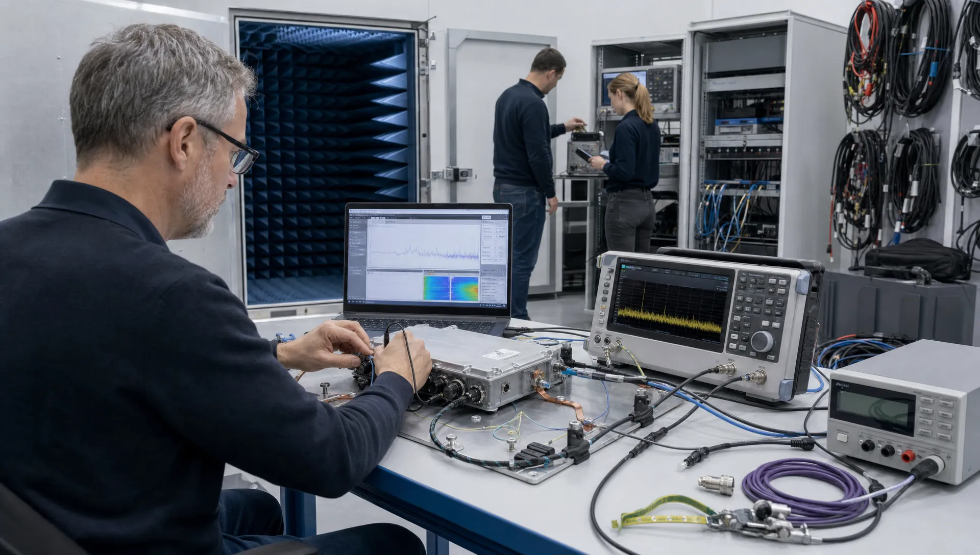
Preparing for electromagnetic compliance testing is a design activity, not a booking task. For technical directors, engineering managers and product owners, the real objective is not to pass one laboratory session by chance. It is to understand how the product behaves electrically, how it interacts with its intended environment and which design decisions could create compliance risk when the product moves from prototype to production.
That preparation matters most in demanding applications: industrial machines, robotics, maritime systems, defence equipment, automotive subsystems, medical devices and connected high-tech products. In these markets, EMC problems can become reliability problems, safety concerns, launch delays or expensive redesigns.
Why electromagnetic compliance testing needs preparation before the lab
A product that works on the bench can still disturb other equipment or suffer from disturbances in the field. EMC assessment is designed to expose that gap. It looks at emissions, meaning unwanted energy leaving the product, and immunity, meaning the product’s ability to continue operating when exposed to external disturbances.
If the first serious EMC discussion happens at the test house, the project has already accepted unnecessary risk. At that stage, board layout, enclosure decisions, cable routing, grounding strategy, power architecture and firmware behaviour may be expensive to change. A useful preparation principle is that electromagnetic compliance testing should confirm known behaviour rather than discover basic architecture weaknesses for the first time.
For teams that need a refresher on the fundamentals, ProMicro’s explanation of what EMC means in product design gives useful context before planning a test campaign.
Start with the product’s electromagnetic risk profile
Preparation starts by defining where the product can generate, conduct or receive electromagnetic energy. This is more practical than beginning with a standards list. Standards matter, but the product’s real operating environment determines where the engineering risks are likely to be.
A motor drive, a wireless sensor node and an embedded controller in a metal machine enclosure all have different risk profiles. The same applies to a battery-powered medical accessory compared with a mains-connected industrial unit. Before electromagnetic compliance testing is planned in detail, the development team should map the product architecture against its use context.
At minimum, define these factors:
- Power source, including mains, battery, DC bus, vehicle supply or external adapter
- Switching elements such as DC-DC converters, inverters, relays, solenoids and motor drivers
- Cable types, cable lengths, connector positions and shield termination concepts
- Analogue interfaces, sensors, measurement inputs and low-level signal paths
- Wireless functions, antennas, radio modules and communication protocols
- User-accessible parts, service ports, enclosure material and grounding approach
This risk profile helps decide which operating modes, product variants and accessories need attention during pre-compliance and formal testing.
Translate standards into testable design requirements
Compliance preparation becomes stronger when standards are translated into engineering requirements early. Instead of simply stating that a product must meet CE requirements, define which emissions limits, immunity levels, environmental assumptions and operating criteria apply.
In the EU, the EMC Directive sets essential requirements for many electrical and electronic products. Products with intentional radio functions may also fall under the Radio Equipment Directive. Sector-specific equipment can involve additional standards or customer requirements, especially in defence, maritime, medical, automotive and industrial environments.
For most products, electromagnetic compliance testing becomes easier to plan when the chosen standards are converted into a test matrix. That matrix should state what will be tested, in which mode, with which acceptance criteria and with which accessories connected.
| Preparation area | What to define | Why it matters |
|---|---|---|
| Applicable framework | CE, RED, UKCA, sector-specific or customer requirements | Prevents late discussion about the wrong test scope |
| Product classification | Intended environment, power type, radio function and installation context | Influences emissions and immunity standards |
| Operating modes | Normal use, worst-case load, communication mode, standby and fault handling | Avoids testing an unrealistically quiet configuration |
| Performance criteria | What counts as acceptable degradation, restart or failure | Makes pass and fail decisions less subjective |
| Accessories | Cables, loads, antennas, power supplies and external devices | Ensures the tested setup represents real use |
Prepare the design, not only the sample
A clean-looking prototype is not automatically a test-ready product. EMC performance is shaped by system architecture and physical implementation. Changing a component value may help in some cases, but many late EMC issues trace back to grounding, return paths, enclosure coupling, cable interfaces or poorly controlled switching energy.
PCB layout and return paths
PCB layout is one of the strongest levers for EMC behaviour. High di/dt loops, interrupted return paths, poorly placed decoupling capacitors and unplanned current paths can all increase emissions or reduce immunity. The placement of connectors, power stages, clock sources and analogue circuits should be reviewed before test samples are released.
This is also where manufacturability and reliability overlap with compliance. ProMicro covers this relationship in more detail in its article on how PCB board design affects reliability and EMC.
Power electronics and analogue interfaces
Switched-mode supplies, motor drives and high-current loads often dominate the EMC risk profile. Edge rates, snubber choices, filtering, shielding, sense routing and thermal behaviour should be reviewed together. In analogue electronics, high impedance nodes and sensor inputs need protection from conducted and radiated disturbances without degrading measurement performance.
If electromagnetic compliance testing is treated as a late gate, these interactions are easy to miss because each discipline may have optimised its own part of the design.
Firmware, modes and enclosure details
Firmware can change the EMC signature of the product. PWM frequency, communication duty cycle, sleep mode transitions, watchdog recovery, logging behaviour and fault handling can all influence emissions or immunity results. The enclosure also matters, especially where apertures, seams, plastic sections, gaskets or cable exits affect shielding and coupling.
The test sample should therefore be reviewed as a complete system: electronics, embedded firmware, mechanics, cabling and intended installation.
Build a pre-compliance plan before booking the lab
Pre-compliance testing is not a substitute for formal assessment, but it can reduce late surprises. It allows the team to compare design options, find obvious problems and improve confidence before paying for a full laboratory slot.
A pre-compliance plan is not a replacement for electromagnetic compliance testing at a qualified test laboratory, but it can make the formal session more productive. Depending on the product, useful tools may include near-field probes, current probes, a spectrum analyser, a line impedance stabilisation network, an ESD generator or conducted immunity equipment. The setup does not need to be identical to the lab, but it must be repeatable enough to compare changes.
The best pre-compliance work focuses on questions that influence design decisions. Is the main radiated peak related to a clock, converter frequency or cable resonance? Does the product reset during ESD because of supply collapse, firmware lock-up or an interface disturbance? Does adding a filter solve the issue or move the problem to another frequency band?
Prepare representative samples and operating modes
A common mistake is sending the cleanest, quietest or most hand-tuned prototype to the test house. That may improve the result for one sample, but it does little to reduce production risk. The tested unit should be representative of the intended design, including PCB revision, enclosure, cabling, firmware version, power supply and accessories.
The sample used for electromagnetic compliance testing should also support realistic worst-case operating modes. For a robot controller, that may include motor activity, sensor polling and active communication. For a maritime unit, it may include long cable harnesses and noisy supply conditions. For an IoT device, it may include radio transmission, charging mode and processor load.
Where several variants exist, decide whether one configuration can credibly represent the family or whether separate tests are required. This decision should be documented, not assumed.
What to bring to the test lab
The laboratory can only test the product efficiently if it receives enough context. Good preparation reduces time spent debugging setup issues, searching for firmware commands or guessing how the product is supposed to behave.
Good electromagnetic compliance testing sessions move faster when the lab has technical information before the first measurement starts. That does not mean sharing unnecessary intellectual property. It means providing enough detail to operate the product correctly, recognise abnormal behaviour and record changes accurately.
| Artefact | Include | Helps with |
|---|---|---|
| Test plan | Standards, modes, acceptance criteria and variants | Keeps scope clear during the session |
| Product description | Intended use, installation context and key interfaces | Helps the lab understand realistic operation |
| Schematics or extracts | Power input, filtering, connectors and sensitive interfaces | Speeds up root cause discussion |
| PCB information | Stack-up, connector locations, ground strategy and critical zones | Supports layout-related diagnosis |
| Firmware notes | Version, operating commands, logs and recovery behaviour | Prevents testing the wrong mode |
| Cable and accessory list | Lengths, shielding, termination and external loads | Improves setup repeatability |
| Change log | Known modifications, previous failures and open issues | Avoids repeating old investigations |
The team should also bring practical items: spare samples, cables, power supplies, adapters, loads, programming tools and someone authorised to make technical decisions.
During the test: control variables and record decisions
A test session can become chaotic if every failure triggers unstructured modification. The goal is to learn quickly without losing traceability. Each change should have a hypothesis, a clear implementation and a recorded result.
During electromagnetic compliance testing, the engineering team should treat every adjustment as a controlled experiment. If ferrites are added, record the type, location and orientation. If firmware settings are changed, record the version and parameter. If a shield connection is modified, photograph it and note whether the change is suitable for production.
This discipline is especially important when a product passes after temporary fixes. A clamp, foil patch or additional capacitor may be useful for diagnosis, but it is not automatically a production solution. The follow-up design change must be assessed for cost, availability, thermal impact, safety, mechanical integration and manufacturability.
When a product fails: diagnose by coupling path
An EMC failure should not be treated as a generic defect. It usually involves a source, a coupling path and a victim or measurement limit. Finding which of those three elements dominates will guide the correction.
A failed electromagnetic compliance testing result is useful only when it leads to a clear hypothesis. For example, a radiated emission peak may come from a clock source, but the cable harness may be the structure that radiates it. An ESD failure may appear as a processor reset, but the real path may be through a connector shield or display interface.
| Test symptom | Possible focus area | Practical investigation |
|---|---|---|
| Radiated peak at a harmonic | Clock, converter edge, cable resonance or return path | Use near-field probing and compare operating modes |
| Conducted emissions on supply | DC-DC converter, input filter or load transient | Check switching frequency, filter damping and current loops |
| Reset during ESD | Ground reference, enclosure path, interface protection or firmware recovery | Observe supply rails, reset lines and communication state |
| Surge or EFT disturbance | Input protection, isolation, cable routing or power architecture | Review protection coordination and current return path |
| Immunity degradation in analogue measurement | Sensor wiring, shielding, filtering or ADC reference | Inject disturbance while monitoring signal chain behaviour |
The correction should be implemented in the design baseline and verified again. If the product is close to production, involve manufacturing and purchasing early so the solution does not depend on unavailable parts or manual assembly steps.
Practical preparation checklist
Use this checklist before confirming the test date. It is deliberately practical, because the strongest EMC preparation usually comes from clear engineering control rather than last-minute laboratory improvisation.
- Define the applicable compliance route and standards with the test house or certification advisor.
- Document the intended environment, installation method, cable lengths and connected equipment.
- Identify likely emission sources and immunity-sensitive circuits in the system architecture.
- Review PCB layout, grounding, filtering, connector placement and shield terminations.
- Confirm firmware versions, operating commands, logs and worst-case modes.
- Prepare representative samples, accessories, loads, antennas, adapters and spare units.
- Decide who can approve modifications during the test session.
- Record all temporary fixes and separate diagnostic changes from production-intent solutions.
- Plan engineering time after the test for analysis, redesign and verification if needed.
This checklist will not guarantee a pass, and it should not be used as a substitute for good design. It does, however, reduce the risk that preventable setup gaps undermine a valuable laboratory session.
Frequently asked questions
How early should electromagnetic compliance testing be planned? It should be considered during architecture and concept development, then refined during schematic, PCB, enclosure and firmware design. The formal lab session may happen later, but the preparation starts much earlier.
Is pre-compliance testing enough for CE marking? No. Pre-compliance is a risk reduction and design verification activity. Formal requirements depend on the product, market and applicable directives or standards.
Which standards apply to my product? That depends on the product type, environment, power source, radio functionality and sector. Industrial, medical, maritime, automotive and defence products can have different expectations, so standards selection should be confirmed early.
Who should attend the EMC test session? Ideally, someone who understands the electronics, firmware, system behaviour and product requirements. The attendee should be able to operate the product correctly and make controlled technical decisions.
Can EMC problems be fixed after a failed test? Often they can, but late fixes may affect PCB layout, enclosure design, cabling, component selection, cost and production planning. Early design attention is usually less disruptive than late correction.
Reduce compliance risk before the lab
For complex electronics, EMC preparation is part of responsible product development. It connects embedded systems, power electronics, analogue design, PCB layout, enclosure choices, firmware behaviour and manufacturing readiness.
If you are preparing electromagnetic compliance testing for a technically demanding product, ProMicro can support the engineering work behind it: system thinking, electronics design, embedded development, prototyping and compliance-aware design decisions. The aim is not to promise a specific certification result, but to reduce technical risk before the product reaches the test chamber, the production line or the field.
