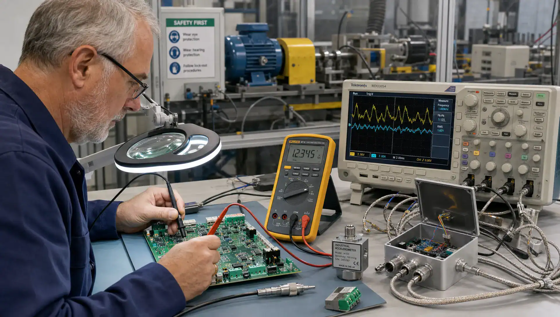
In industrial products, analogue electronics often determines whether the system measures the right value, reacts at the right moment and remains stable outside a controlled lab. A prototype can appear functional when signals are clean, temperatures are moderate and cables are short, yet fail when it is installed next to motors, long wiring, moisture, vibration or high-current switching.
For engineering managers, CTOs and product owners, the lesson is direct: accuracy and reliability cannot be added at the end of development. They are created through architecture, component selection, PCB layout, filtering, calibration, testing and manufacturing preparation. That is especially true when sensors, power electronics, wireless communication and embedded firmware need to work together in one compact product.
Why analogue electronics still matters in industrial product design
Industrial electronics exists at the boundary between the physical world and digital decision-making. Temperature, pressure, current, vibration, position, flow and biomedical signals all start as physical quantities. Before software can use them, the product must convert small, imperfect signals into stable digital information.
For product teams, analogue electronics is the part of the design that decides how much real-world behaviour is preserved, distorted or lost before the microcontroller ever sees it. A poor analogue front end can make excellent firmware look unreliable because the data entering the system is already noisy, shifted or unstable.
| Design area | What it influences | Typical industrial risk |
|---|---|---|
| Sensor interface | Signal range, impedance and protection | Incorrect readings, damaged inputs or slow response |
| Signal conditioning | Gain, filtering and bandwidth | Noise, delay or loss of important signal detail |
| Reference and ADC design | Measurement stability and resolution | Drift, inconsistent calibration or poor repeatability |
| Grounding and shielding | Noise coupling and EMC behaviour | Field failures near motors, radios or switching supplies |
| PCB layout | Parasitics, leakage and thermal behaviour | Prototype works, production units vary |
Digital electronics may make the final decision, but the quality of that decision depends heavily on the integrity of the analogue path.
From real-world requirements to circuit architecture
Define the operating context first
A robust analogue electronics design process starts with requirements that describe the real operating environment, not only the intended function. The design team needs to understand signal amplitudes, source impedance, bandwidth, accuracy targets, response time, temperature range, cable length, installation method, expected disturbances and safety boundaries.
Those details influence architecture. A pressure sensor mounted inside a protected enclosure has different needs from a high-impedance sensor connected through a long cable on a machine. A battery-powered maritime device faces different leakage, corrosion and transient risks from a stationary industrial controller inside a cabinet.
This is where product context matters. ProMicro often treats electronics development as a system problem, combining hardware, embedded firmware, PCB design, enclosure thinking and production preparation rather than treating the analogue section as an isolated schematic.
Select the right signal path
Once the environment is clear, the circuit architecture can be chosen with fewer assumptions. That may involve instrumentation amplifiers for differential sensor signals, transimpedance amplifiers for current-output sensors, isolation barriers for safety or noise control, low-pass filtering for anti-aliasing and input protection for ESD or wiring faults.
The aim is not to make the most complex circuit. It is to create a signal path with the right precision, robustness and manufacturability for the application. The same thinking is discussed more broadly in ProMicro’s article on how electronic design choices shape product reliability, where early architecture decisions are shown to influence long-term product behaviour.
Accuracy is a system property, not a data sheet value
In accurate products, analogue electronics is treated as an error budget, not as a collection of impressive component specifications. A 16-bit ADC does not guarantee 16-bit useful performance if the reference voltage drifts, the input amplifier saturates, the PCB leaks at high humidity or the sensor tolerance dominates the result.
An error budget helps the team identify which effects actually matter. It also prevents over-engineering. In some systems, thermal drift is the dominant problem. In others, common-mode noise, offset voltage, resistor tolerance or calibration procedure may be more important.
| Error source | Effect on product behaviour | Practical design response |
|---|---|---|
| Sensor tolerance | Absolute value differs between units | Calibration, sensor selection or compensation model |
| Amplifier offset and drift | Measurement shifts over time or temperature | Low-drift components, auto-zero options or firmware correction |
| Reference instability | ADC readings move together | Stable reference design, filtering and thermal placement |
| PCB leakage | Errors in high-impedance circuits | Guarding, spacing, material choice and cleanliness control |
| Quantisation and noise | Readings fluctuate or lack resolution | Filtering, averaging, bandwidth control and ADC selection |
This approach is useful for technical leaders because it links design effort to product risk. Instead of asking whether the circuit is “accurate enough” in general terms, the team can decide which tolerances are acceptable for the user, the machine and the business case.
Designing for noise, EMC and power integrity
Good analogue electronics separates useful signals from disturbances that the product will encounter in service. These disturbances can be conducted through power lines, coupled through cables, radiated from nearby transmitters or created internally by switching converters, motor drives, relays and digital clocks.
EMC-aware design starts before formal testing. Input filters, transient protection, connector strategy, cable shielding, grounding approach and PCB return paths all influence whether the product behaves predictably during immunity tests and field use. Standards such as the IEC 61000-4 series are often used to assess immunity to phenomena such as electrostatic discharge, electrical fast transients and surge, but the design work has to begin much earlier than the test booking.
Power integrity is just as relevant. Analogue references, sensor supplies and amplifier rails may need filtering, local regulation, careful decoupling and separation from noisy loads. When power electronics is part of the product, the analogue design must be coordinated with switching frequency, current loops, thermal behaviour and PCB layout. ProMicro explores related design trade-offs in its article on designing power electronics for reliability, EMC and scale.
PCB layout turns analogue intent into real performance
A schematic can show the correct topology, but the PCB decides whether the circuit behaves as expected. In sensitive circuits, layout parasitics, return currents, coupling capacitance, trace resistance, thermal gradients and component placement can change the measurement result.
For analogue electronics in industrial products, layout decisions often include separating high-current paths from low-level signals, keeping ADC references quiet, controlling impedance where needed, placing filters close to connectors, routing differential signals symmetrically and avoiding noisy digital return currents through sensitive measurement areas.
Mechanical integration also matters. Connector placement, enclosure material, cable entry, heat sources and service access can all affect signal integrity and reliability. A layout that is electrically correct but difficult to assemble, test or protect may still create problems during manufacturing or maintenance.
This is why PCB work should not be treated as the final drawing step after design is “finished”. For products intended for long-term use, the board is part of the system architecture. ProMicro’s article on circuit board design decisions that shape reliability expands on this relationship between layout, materials, manufacturing and field performance.
Production readiness requires tolerance and lifecycle thinking
In production, analogue electronics must remain stable across component batches, assembly variation, temperature spread, ageing and maintenance conditions. A circuit that works on a manually tuned prototype can become expensive if every unit needs excessive adjustment or specialist handling.
Manufacturing readiness starts with design choices. Component tolerances should be realistic. Calibration points should be accessible and automatable where possible. Test limits should be based on the product’s actual performance requirements, not only on individual component data sheets.
Lifecycle management also deserves attention. Industrial products often remain in the field for many years, so component availability, second-source options and redesign risk are commercial issues as well as technical ones. Choosing a specialised amplifier, ADC or sensor interface without considering long-term supply can create avoidable redesign work later.
For OEMs and machine builders, these decisions affect warranty cost, serviceability and production scaling. A stable analogue design reduces variation between units and gives embedded firmware a cleaner, more predictable foundation.
Testing should reflect field conditions, not only lab success
Analogue electronics testing should connect directly to the earlier error budget and environmental assumptions. Bench tests are necessary, but they should not stop at a clean supply, short cables and room temperature.
A practical test plan may include temperature sweeps, supply variation, load changes, cable length testing, injected noise, EMC pre-compliance checks, calibration repeatability, long-duration drift measurements and comparison against known physical inputs. For products used in robotics, maritime systems, medical devices, defence applications or machine building, these tests help reveal issues that a functional prototype may hide.
Testing also needs firmware involvement. Filtering, sampling rate, fault detection, diagnostics and calibration storage all influence the final measurement chain. If hardware and software are developed separately, teams can miss interactions such as aliasing, start-up instability, timing conflicts or poor fault handling.
This is why an integrated development approach is valuable. Products that combine sensing, control, connectivity and power conversion need design decisions across disciplines. ProMicro covers the broader system view in its article on embedded systems that operate in demanding real-world conditions.
When to involve a specialist development partner
For OEMs, analogue electronics is often where hidden risks appear late: unexplained measurement spread, EMC sensitivity, unstable readings, calibration drift, noise near motor drives or prototypes that behave differently after enclosure integration. These issues are rarely solved by changing one component at the end.
A specialist partner can add value when the product includes low-level sensing, precision measurement, harsh environments, mixed-signal PCB design, high-current switching, wireless connectivity, safety-related boundaries or certification-sensitive behaviour. The value is not only extra capacity. It is the ability to recognise interactions between hardware, firmware, power, PCB layout, enclosure design, testing and manufacturing.
ProMicro supports technically demanding product development across embedded systems, power electronics, analogue design, PCB design, prototyping and preparation for volume manufacturing. The goal is to reduce technical risk early, make hidden requirements visible and create electronics that are more likely to perform reliably in real applications.
Frequently asked questions
Why is analogue design still important when products are mostly digital? Digital systems depend on physical inputs, power quality and stable references. If the analogue front end produces noisy, drifting or distorted information, the embedded software cannot make reliable decisions.
What causes analogue measurement problems in industrial products? Common causes include poor grounding, inadequate filtering, unsuitable sensor interfaces, unstable reference voltages, thermal drift, PCB leakage, cable coupling and noise from motors or switching power supplies.
Can EMC issues be solved during certification testing? Certification testing can reveal problems, but it is rarely the best moment to fix them. EMC behaviour is shaped by architecture, PCB layout, filtering, grounding, enclosure design and cabling decisions made much earlier.
How early should analogue specialists be involved? They should be involved before architecture and PCB layout are fixed, especially when the product uses precision sensors, long cables, motor drives, wireless communication or demanding operating environments.
Discuss your analogue design risks with ProMicro
If analogue electronics is central to your product’s accuracy, safety or reliability, early engineering decisions will have a direct effect on certification readiness, production scaling and field performance. ProMicro can support your team with specialist electronics development, embedded systems expertise, PCB design, prototyping and manufacturing preparation.
To discuss a technically demanding product or strengthen your internal development capacity, visit ProMicro and involve an engineering partner before avoidable design risks become expensive redesign work.