Prototype circuit board assembly should be specified not only to produce working hardware, but also to support controlled engineering changes. During development, teams may need to replace components, adjust analogue filters, investigate switching behaviour or revise interfaces. If those changes are difficult to execute or poorly documented, a useful prototype can become an unreliable source of test results.
The objective is not unlimited rework. It is to define which interventions the build must support, how they will be performed and what evidence is required before a modified board returns to testing. That requires decisions across PCB layout, assembly, embedded firmware and configuration control.
Define what the prototype must prove
Start with the engineering questions behind the build. A power-stage prototype intended to compare gate-drive settings needs different access from a sensor interface being evaluated for noise performance. A representative system prototype may need both, without compromising enclosure integration or EMC behaviour.
Distinguish the hardware being ordered. A bare-board prototype is the fabricated PCB without fitted components. It can support dimensional, stack-up or fabrication checks, but cannot validate an operating circuit. A PCB assembly includes mounted components and can support electrical testing once inspected, programmed and safely powered.
For prototype circuit board assembly, identify the likely changes before releasing the layout. Record the circuits involved, candidate component values, package alternatives and measurements needed to judge each change.
Also distinguish three activities. Rework brings an assembly back into its specified condition, such as correcting a solder defect. A modification deliberately changes its configuration. Repair addresses damage or defects through an approved restoration method. Calling every intervention “rework” can obscure whether the resulting board still matches the released design.
This distinction matters when accepting hardware and interpreting test results. A correctly repaired board and an intentionally modified board require different records.
Specify prototype circuit board assembly with a modification matrix
Give the assembler and development team a short matrix describing expected interventions. “Must be easy to rework” is too vague to guide package placement, tooling or inspection.
| Circuit or feature | Expected intervention | Requirement to specify |
|---|---|---|
| Gate-drive network | Exchange resistors during switching evaluation | Tool access, nearby component protection and defined measurement points |
| Analogue input filter | Compare resistor and capacitor values | Accessible footprints and recorded fitted values |
| Current measurement | Replace a shunt or amplifier | Thermal access, Kelvin connection integrity and recalibration checks |
| Communications interface | Evaluate termination or protection options | Defined population variants and signal-integrity checks |
| Embedded controller | Update firmware and recover failed programming | Accessible programming interface and documented recovery procedure |
Assign each intervention an owner and an approval route. A technician should not have to decide whether changing a protection component is an acceptable experiment.
Identify assemblies that must remain unmodified. For example, a reference unit can help distinguish an actual circuit improvement from damage introduced during repeated heating. Boards intended for representative environmental or compliance testing also need a clearly controlled configuration.
Do not make every circuit configurable. Extra jumpers, connectors and component options consume space and may introduce parasitic effects. Concentrate flexibility where uncertainty is highest, then document the compromises.
Design access without undermining electrical performance
Allow for tools, heat and mechanical support
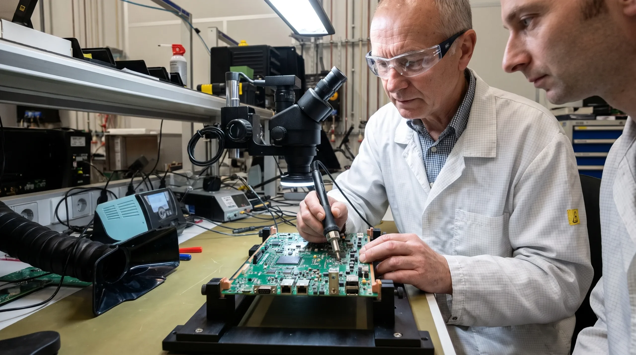
Check access using the actual component arrangement, not only the copper layout. Hot-air nozzles, soldering tools, inspection equipment and fixtures need space above and around the target. Tall connectors, heatsinks and enclosure features can block that access after assembly.
Double-sided placement needs particular attention. Heating a component on one side may disturb joints or temperature-sensitive parts on the other. Large copper areas can also make local heating difficult, while heavy components may need support during removal and replacement.
A layout review for prototype circuit board assembly should therefore include a rework-access check alongside normal design-for-manufacture checks. Confirm the proposed approach with the assembly partner before freezing placement.
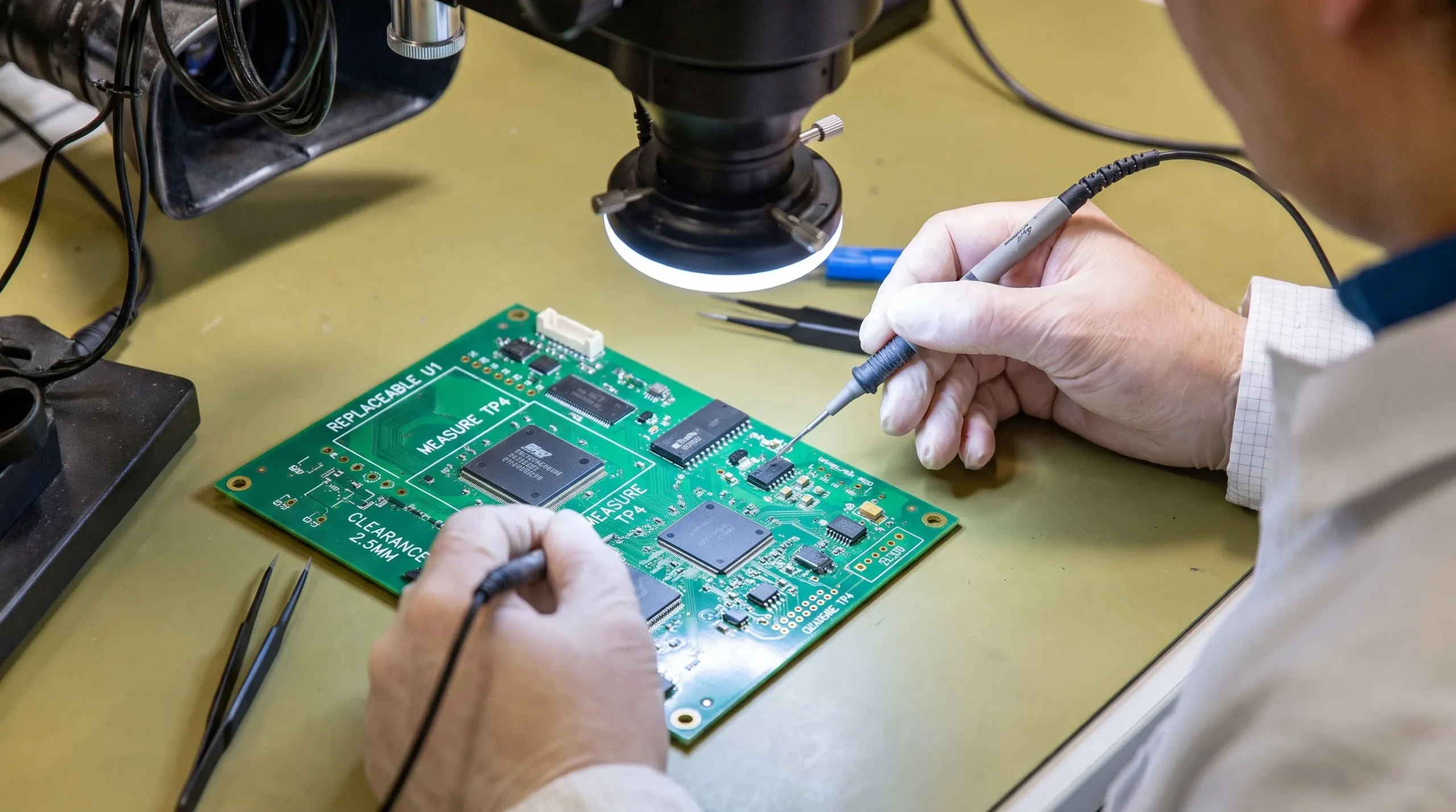
There is no universal clearance that makes every package reworkable. Required access depends on package geometry, tooling, thermal mass and neighbouring materials. Put agreed restrictions into the assembly notes rather than relying on an informal conversation.
Keep experimental features electrically credible
Provide measurement access where it is needed, but avoid treating test points as electrically invisible. Added stubs can affect fast signals. Long connections in a switching loop can increase inductance and alter overshoot. Uncontrolled ground connections can corrupt low-level analogue measurements.
Use suitable probing arrangements and preserve critical return paths. Where alternative component values are expected, retain the intended topology rather than introducing long flying leads as the default adjustment method.
For high-voltage circuits, access must not compromise insulation distances, barriers or safe probing arrangements. Define discharge, isolation and stored-energy checks before anyone connects instruments or applies heat.
A temporary modification can be useful for diagnosis without being representative of the final product. Label that limitation explicitly in the test record.
Release a build pack that describes the intended variants
The manufacturing package must explain both the baseline build and permitted alternatives. For prototype circuit board assembly, the assembler needs enough information to distinguish an intentional omission from a missing component or incorrect population.
A practical release pack includes:
- Fabrication data: agreed manufacturing files, drill information, stack-up and material requirements, with a consistent revision identifier.
- Assembly data: component coordinates, assembly drawings, polarity information and relevant mechanical restrictions.
- Bill of materials: manufacturer part numbers, approved alternatives, package details and clearly identified do-not-populate positions.
- Variant definitions: a separate population record for each configuration, including fitted values and link positions.
- Engineering references: schematics and relevant layout information needed to assess changes, subject to agreed information controls.
- Process notes: soldering requirements, sensitive components, coating stages, adhesive restrictions and special handling instructions.
- Verification requirements: inspection, programming, electrical tests and records required before delivery.
Keep all files under the same release control. A revised BOM sent by email after the assembly drawing has been approved creates an avoidable ambiguity.
Specify whether the supplier may substitute parts and which changes require engineering approval. A nominally equivalent capacitor, MOSFET or oscillator can behave differently in the circuit.
The wider considerations in preparing a PCB design for prototyping and volume build remain relevant. Here, the additional requirement is to make every planned intervention traceable to an agreed configuration.
Agree a controlled rework process
Do not specify a universal soldering temperature or maximum number of rework cycles without supporting evidence. Suitable limits depend on the laminate, package, solder alloy, component history and local thermal conditions.
Instead, require the supplier to propose a process appropriate to the assembly. Where needed, that includes preheating, temperature measurement, board support, shielding and inspection after the operation. Temperature-sensitive connectors, sensors and nearby plastics must be considered as well as the component being changed.
For prototype circuit board assembly, the process specification should also address moisture-sensitive devices. Storage, floor-life tracking and any drying requirements must follow applicable component guidance and agreed procedures. Repeatedly heating an assembly is not a substitute for controlling its moisture exposure.
The IPC standards framework provides useful references: IPC-7711/7721 covers rework, modification and repair, while J-STD-001 and IPC-A-610 address soldered assembly requirements and acceptance. Agree the applicable revisions, product class and any project-specific exceptions in the contract. Naming a standard does not by itself establish supplier capability or product compliance.
Discuss coatings, potting compounds, underfill and adhesives before assembly. Applying them too early can prevent access or make removal destructive. Conversely, postponing them may leave a prototype unrepresentative of the intended thermal, vibration or environmental behaviour.
Record each significant heating operation where the history could affect later decisions. Escalate lifted pads, damaged solder mask, laminate damage or uncertain internal connections for engineering disposition rather than concealing them with further work.
Define acceptance before and after modification
Separate workmanship from functional evidence
A board can meet visual workmanship criteria and still fail electrically. It can also function during a short bench test while containing a defect that threatens reliability. Specify inspection and functional verification separately.
Before first power-up, agree checks appropriate to the circuit. These may include polarity verification, inspection for shorts, resistance checks and confirmation that the intended population variant has been built. Apply controlled bring-up procedures suitable for the available energy and product hazards.
For prototype circuit board assembly, define the verification required after each category of intervention. Replacing an analogue filter component does not require the same checks as replacing an isolation component or power semiconductor.
Inspection methods must match the joints involved. Optical inspection cannot fully establish the condition of hidden connections beneath packages. X-ray inspection may provide useful evidence for selected defects, but it does not replace functional testing or prove every aspect of joint quality.
Retest the affected system behaviour
Use a change-to-test matrix so the team knows which evidence has become invalid.
| Change made | Examples of checks to reconsider |
|---|---|
| Gate resistor or switching device | Switching waveforms, losses, protection response and EMC behaviour |
| Current shunt or measurement amplifier | Offset, gain, calibration and overcurrent thresholds |
| Power-supply feedback component | Regulation, stability, transient response and startup |
| Interface protection or termination | Communications performance, signal quality and relevant immunity behaviour |
| Connector or enclosure connection | Continuity, mechanical fit, shielding and protective connections where applicable |
These are examples, not a complete qualification plan. Select tests from the product requirements and failure risks. If a change affects safety-related behaviour, obtain the necessary engineering approval before returning the board to service.
Keep each modified assembly identifiable
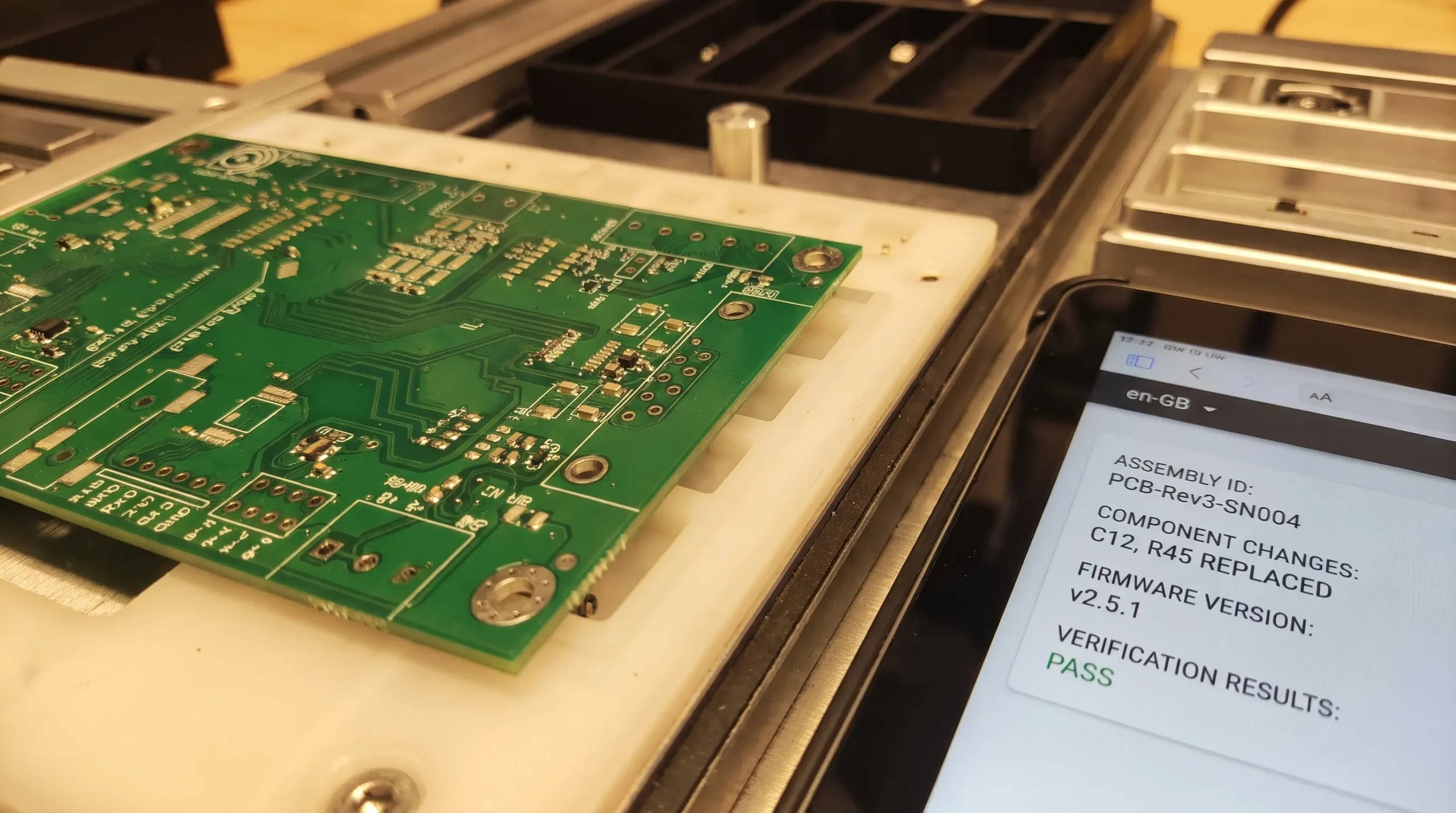
Assign a unique identifier to every board and link it to the PCB revision, assembly revision, population variant and firmware version. Without board-level identity, a successful measurement may be impossible to reproduce.
Each modification record should identify the affected reference designators, original and replacement parts, reason for the change, authorisation, operator and date. Include inspection results and relevant thermal-process records. Photograph physical modifications where that helps another engineer understand the configuration.
Configuration control is especially important when prototype circuit board assembly supports parallel hardware and firmware development. A changed current-sense gain can invalidate firmware thresholds even when the software image itself is unchanged. Store calibration data and parameter sets with the hardware record where relevant.
Temporary wires and cut tracks need documented endpoints and a clear status. State whether they are permitted only for diagnosis or approved for a defined test programme. Do not let a successful experiment silently become the new baseline.
Keep at least one reproducible configuration for comparisons where practical. When several boards have different component values, firmware builds and rework histories, comparing their results without a configuration record creates false conclusions.
Before transferring a validated change into the next revision, update the schematic, BOM, layout and tests together. The bench modification is evidence for the design decision, not a replacement for releasing it properly.
Ask suppliers to quote the engineering work explicitly
A comparable quotation needs more than board dimensions, component count and quantity. Separate initial assembly from optional modifications, inspection, programming, test-fixture work and engineering support.
Ask how the supplier will assess rework feasibility, manage unexpected damage and obtain approval before exceeding the agreed scope. Clarify ownership of replacement components, spare bare boards, unused material and process records.
The cost and lead time of prototype circuit board assembly depend on package complexity, thermal demands, component availability and the verification required. A small quantity does not necessarily mean a simple process. Fine-pitch devices, hidden joints, heavy copper and limited access can increase preparation effort.
Spare components may be needed for setup, replacement or destructive investigation. Agree quantities with the assembler rather than assuming the exact fitted quantity is sufficient. Also check whether the proposed substitute parts remain available for the intended production lifecycle.
When comparing local and overseas providers, consider the complete engineering loop. Shipping, customs where applicable, technical communication, secure handling of design data and the ability to return boards for investigation can matter more than the assembly line item. Geography alone does not establish quality.
The broader criteria for choosing circuit board assembly services help assess capability. For this build, request specific evidence of suitable tooling, process control and documentation for the interventions you expect.
Include a rework clause in the assembly specification
A short contractual clause can turn the preceding decisions into a clear instruction. It should refer to controlled project documents rather than attempt to contain every technical detail.
For prototype circuit board assembly, a starting point is:
Build each assembly to the released manufacturing package and assigned population variant. Perform only the modifications authorised in the controlled modification register. Before work begins, confirm access, component handling requirements, the proposed thermal process and applicable inspection criteria. Record the assembly identifier, affected components, replacement part details and intervention history. Obtain engineering approval for substitutions, conductor repairs, pad damage or deviations from the agreed method. Complete the inspections and electrical tests assigned to the change category before releasing the assembly. Mark diagnostic-only configurations clearly and do not present them as representative production hardware.
Adapt this wording to the product, supplier responsibilities and acceptance framework. It is not a substitute for an approved process or detailed test specification.
Add a disposition route for boards that cannot meet the original requirements. Possible outcomes include approved diagnostic use, further investigation or rejection. Keeping such hardware available for learning can be sensible, provided its limitations remain visible and it is excluded from inappropriate testing.
Retire prototype workarounds before production
A successful modification should normally become a controlled design change, not a permanent instruction to patch every production board. Review its effect on layout, assembly yield, test coverage, serviceability and component availability.
Prototype circuit board assembly provides evidence for that decision, but a repeatedly modified unit is not automatically representative of an untouched production build. Rework history, temporary wiring and missing coatings can all affect the relevance of its results.
Build representative verification units when the design has stabilised. Reassess EMC, thermal performance, protection behaviour and environmental requirements according to the changes made. Passing an earlier test does not automatically cover a later configuration.
ProMicro combines embedded systems, power electronics, analogue electronics, PCB design and mechanical integration with prototyping and manufacturing support. That integrated view helps teams decide which experiments are useful and which results still need confirmation before production release.
Frequently asked questions
Should every prototype component be easy to replace? No. Prioritise uncertain circuits and likely tuning points. Making every component accessible can increase board size or compromise electrical performance. Some changes are better evaluated on a dedicated test board or a new PCB revision.
Can a reworked prototype be used for compliance testing? It depends on the modification, configuration and test purpose. Diagnostic tests can use modified hardware, but formal assessment needs an agreed representative configuration. Discuss significant changes and their effect on existing evidence with the responsible compliance team or test laboratory.
How many rework cycles can a board tolerate? There is no universal safe number. Capability depends on the board materials, package, process and accumulated exposure. Define limits using supplier and component guidance, process evidence and inspection, then track the actual history.
What should be supplied when requesting a quote? Provide the controlled manufacturing pack, quantities, population variants, expected modifications, inspection requirements and functional test scope. Identify special thermal, safety, environmental or information-security constraints so the supplier can assess feasibility before committing.
To review the rework requirements for your next prototype, discuss your project with ProMicro's engineers. A practical starting point is your intended modifications, current build documentation and the evidence needed to move from bench testing towards a production-ready design.