
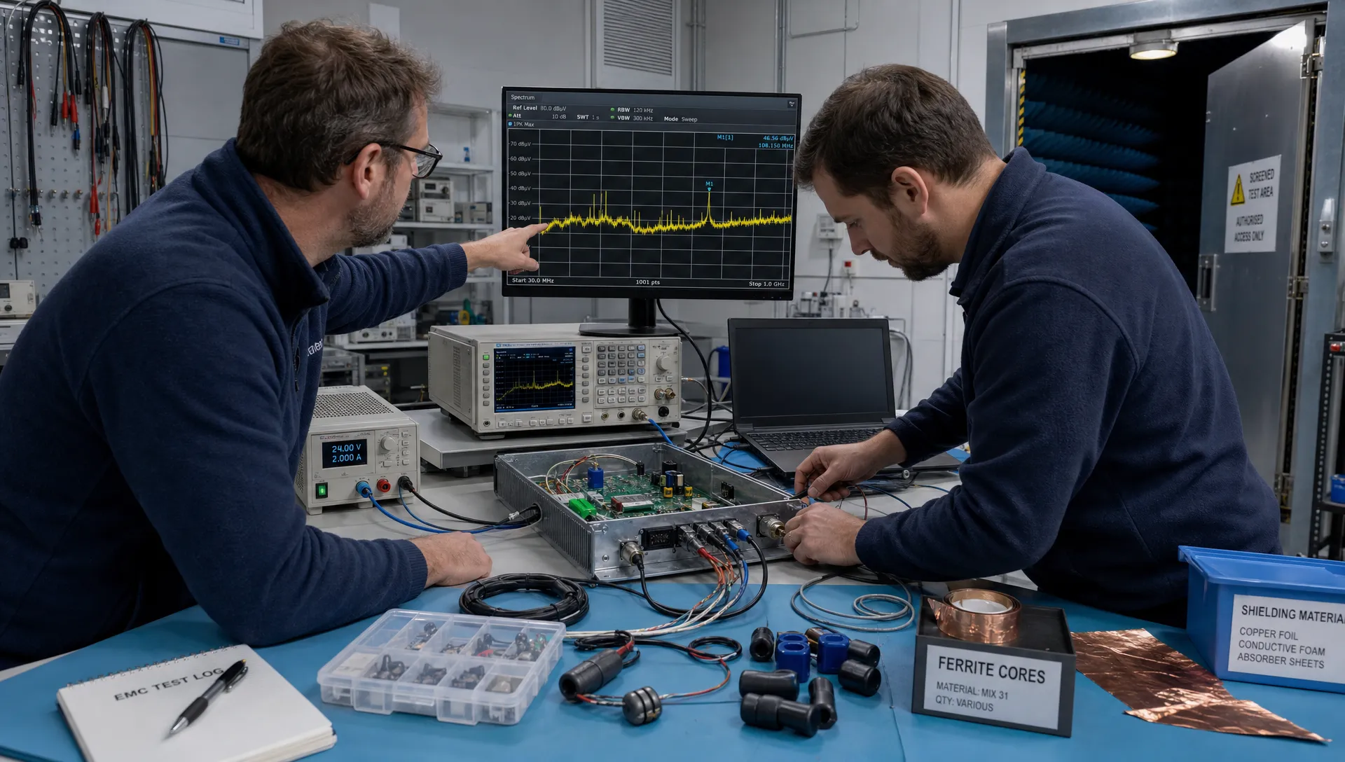
EMC testing is often treated as the final gate before CE marking, but for professional electronics it is better understood as a set of engineering checks that should influence architecture, PCB layout, cabling, firmware and enclosure decisions long before the formal lab visit. For CTOs, engineering managers and product owners in high-tech, defence, maritime, robotics, machine manufacturing or medical markets, the objective is not to pass a test once. It is to build electronics that remain reliable in the electromagnetic environment where they will be installed, serviced and manufactured.
Late surprises usually cost more than a retest slot. They can force PCB redesigns, enclosure changes, cable modifications, firmware workarounds, supply-chain discussions and project delays just when the product team expects to move towards release. Better preparation turns EMC from a late compliance concern into a controllable engineering risk.
How EMC testing fits into the development process
Formal compliance tests are carried out against defined standards, but the behaviour measured in the chamber is created throughout the project. The choice of power architecture, processor clocking, grounding concept, switching frequency, cable routing, shielding and software operating modes all shape emissions and immunity. If these decisions are made without considering the final test environment, the lab becomes the first place where hidden assumptions are exposed.
Planning for EMC testing does not mean designing only for the minimum requirement. It means understanding which disturbances the product may emit, which disturbances it must tolerate and which operating modes need to be demonstrated. For teams still defining the basics, ProMicro has a separate explanation of what EMC means in product design and why it affects product reliability as well as compliance.
| Development phase | EMC preparation focus | Typical output |
|---|---|---|
| Concept | Product environment, power sources, cables, enclosure assumptions | Initial risk overview |
| Architecture | Grounding, partitioning, interfaces, safety boundaries | System-level EMC strategy |
| Schematic and PCB | Filtering, return paths, layout constraints, component placement | Reviewable design rules |
| Prototype | Representative operating modes, harnesses, loads, firmware | Pre-compliance evidence |
| Formal test | Test plan, samples, accessories, configuration control | Traceable test campaign |
| Production | Approved components, process controls, change management | Repeatable product behaviour |
This staged approach helps avoid a common problem: a prototype that functions in the lab, but represents neither the final installation nor the final manufacturing configuration.
Start with the real electromagnetic environment
Good preparation for EMC testing begins with the use case, not the chamber. A medical device, a robot controller, a maritime monitoring unit and a vehicle-mounted module may contain similar electronics, yet face very different cables, grounding structures, power disturbances, radio transmitters, switching loads and installation practices. A compliance test based on the wrong environment can create false confidence or unnecessary redesign.
Define the product context before detailed design choices become fixed. This should include how the electronics are powered, what they connect to, which cables leave the enclosure, where users touch the product, how close it operates to motors or converters and whether wireless communication is part of normal operation.
Translate the environment into requirements
The practical requirement set should not stop at a generic standard list. It should describe the product states that matter during tests and how the equipment should behave when exposed to disturbances. Examples include normal operation, degraded but safe operation, automatic recovery, logged fault conditions or a controlled reset.
A useful early checklist includes:
- Supply type, voltage range, grounding and expected transients
- Cable lengths, shielding, connector types and installation constraints
- Nearby noise sources such as drives, contactors, radios or high-current switching
- Required operating modes during emissions and immunity tests
- Acceptance criteria for safety, control behaviour, communication and recovery
For CE-marked products in Europe, the EMC Directive sets essential requirements for electromagnetic compatibility. The exact harmonised standards and test levels still depend on the product category, intended environment and other applicable directives, such as RED for radio equipment.
Prepare the design before the lab booking
A product that enters EMC testing with unresolved system questions is expensive to debug. The chamber may identify a failing frequency band or immunity weakness, but it will not automatically explain whether the root cause is PCB layout, a cable resonance, enclosure bonding, a switching converter, firmware timing or a missing return path. Preparation means reducing the number of plausible root causes before the formal campaign begins.
Early design reviews should focus on coupling paths. Noise can be conducted through supply lines, radiated from loops and cables, injected through interfaces or created by fast edges inside the product. In power electronics and motor drive applications, switching nodes, current loops and thermal constraints must be considered together because a cleaner layout that cannot be cooled, assembled or serviced is not a viable solution.
Architecture, PCB, enclosure and cables must agree
EMC is rarely solved by one component. Filters need a low-impedance reference. Shielded cables need clear bonding decisions. Split grounds can help or harm depending on return currents. A metal enclosure can improve containment only if seams, penetrations and connectors are treated as part of the electrical system.
This is why PCB layout, mechanical integration and system engineering need to be aligned. If you are reviewing a design before prototype build, ProMicro’s article on EMC design principles for demanding environments gives more detail on partitioning, grounding, filtering and layout discipline.
Firmware and operating modes matter
Embedded firmware affects EMC behaviour more than many teams expect. Processor sleep states, PWM patterns, communication bursts, sensor sampling and fault handling can change emissions and immunity sensitivity. A product may pass in an idle demonstration mode, then fail when the motor drive, wireless module or display is active.
Before testing, define firmware modes that represent real operation and stress the relevant subsystems. The test operator should not have to guess how to put the product into maximum activity, safe state or recovery mode.
Build prototypes that represent the product you will sell
A surprising number of EMC testing failures are created by non-representative prototypes. A hand-wired cable, missing enclosure gasket, temporary power supply, open debug connector or substitute component can change the electromagnetic behaviour enough to make test results difficult to interpret. Sometimes a prototype fails because it is not yet the product. Sometimes it passes for the same reason.
Representative does not always mean production-perfect. It means that known differences are documented and judged for EMC relevance. If the final product uses a specific enclosure, cable shield termination, connector plating, PCB stack-up or power supply arrangement, the test sample should reflect those choices or the deviation should be consciously accepted as a risk.
| Late surprise | Why it happens | Preparation action |
|---|---|---|
| Radiated emissions from cables | Interface currents turn a cable into an antenna | Define cable routing, shielding and common-mode filtering early |
| Conducted emissions on supply | Switching converter noise reaches the power input | Review input filter damping, layout and source impedance |
| ESD reset at user interface | Discharge path crosses sensitive logic or reset circuitry | Control enclosure paths, grounding and interface protection |
| Immunity failure during motor activity | Firmware or control loops cannot tolerate disturbance | Test realistic operating states and recovery behaviour |
| Different result after PCB update | Layout change altered return paths or parasitics | Apply configuration control and EMC review to layout revisions |
| Pass in prototype, fail in production | Component, cable or assembly process changed | Define approved variants and manufacturing controls |
Documenting these details also helps the test lab. A clear sample description, configuration record and set of operating instructions can save hours of uncertainty during a booked test slot.
Use pre-compliance measurements to find issues early
Pre-compliance work is not a substitute for EMC testing at an accredited lab, but it is one of the best ways to prevent avoidable late failures. Simple measurements with near-field probes, current probes, a spectrum analyser, a LISN where appropriate and controlled bench setups can reveal dominant noise sources before the formal campaign. The aim is not to produce a certificate-quality result. The aim is to learn where margin is weak.
Pre-compliance is especially useful after the first integrated prototype, after major PCB revisions and after changes to the enclosure, cable set or power stage. It can also support design trade-offs. For example, if a switching converter creates a strong emission at a problematic frequency, the team can compare layout changes, snubber values, spread-spectrum settings, filter options or shielding approaches before the schedule depends on a single lab booking.
The strongest value comes when measurements are repeatable. Keep the bench setup consistent, record the sample version, photograph cable positions and measure after one change at a time. Even approximate evidence becomes useful when it shows trends.
Make the formal test campaign controllable
A formal EMC testing campaign should be treated like an engineering experiment with configuration control, not like a black-box appointment. Before the visit, agree the applicable standards, product modes, acceptance criteria, sample configuration, auxiliary equipment and responsibilities with the lab. For complex products, this discussion may reveal missing adapters, unsafe operating conditions, unclear monitoring methods or unrealistic test durations.
The test plan should also define what will be monitored. In some products, a short communication dropout is acceptable if it recovers automatically. In safety-related machine control, the same dropout may be unacceptable. In defence, maritime or industrial projects, customer specifications may add requirements beyond the usual commercial product route.
What to bring to the lab
Preparation reduces pressure when a failure occurs. Bring the materials needed to operate, observe and, if appropriate, make controlled diagnostic changes to the sample.
A practical lab pack may include:
- Final or documented prototype samples with serial numbers and revision details
- Power supplies, loads, fixtures, cables and auxiliary devices used in normal operation
- Firmware images, configuration tools and instructions for all required operating modes
- Block diagrams, schematics, PCB stack-up notes and interface descriptions for debugging
- Spare boards, filters, ferrites, shielding materials and approved diagnostic parts
- A change log template so every modification and result is traceable
Not every project should be modified during formal testing. In certification campaigns, uncontrolled changes can invalidate evidence. Still, having the right information and parts available helps the team decide whether to investigate, repeat, stop or schedule a planned redesign.
Debug with evidence, not trial and error
When EMC testing reveals a failure, the fastest answer is not always the most reliable one. Adding ferrites, copper tape or capacitors can be useful for diagnosis, but unmanaged fixes often hide the mechanism rather than solve it. If a quick patch passes one sample, the product team still needs to know whether it is manufacturable, stable over temperature, compatible with safety requirements and suitable for lifecycle support.
Good debugging starts with the failure signature. Is the problem narrowband or broadband? Does it follow a clock, switching frequency or cable movement? Does it appear only in one firmware state? Does a disturbance cause a reset, a communication error, a sensor offset or unsafe actuator behaviour? These observations guide the next measurement.
Change one variable at a time where possible. Record the configuration, result and reasoning. If a mitigation works, translate it into a design action: PCB layout change, filter redesign, enclosure bonding update, firmware timing change, connector specification or installation instruction. This turns a lab workaround into a controlled product decision.
Link test learning to manufacturing and lifecycle control
The value of EMC testing is highest when the learning is carried into production readiness. A product can pass a formal sample and still become risky if later purchasing, firmware, enclosure, cable or assembly changes are made without EMC review. This is especially relevant for products with long service lives, controlled markets or field maintenance obligations.
Manufacturing preparation should define which parts and variants are approved, which assembly steps affect shielding or grounding and which changes require engineering approval. For example, a different cable supplier, connector finish, PCB stack-up, gasket material or DC-DC converter can alter the electromagnetic behaviour. Firmware updates can also change timing, duty cycles and communication patterns.
Lifecycle management is not paperwork for its own sake. It protects the design intent that allowed the product to pass tests and perform reliably in the field. ProMicro’s article on embedded design decisions that affect EMC, safety and lifecycle explores this connection in more depth.
Frequently Asked Questions
When should we start planning EMC testing? Start during concept and architecture definition, not after the first prototype is finished. Early planning helps identify relevant standards, operating modes, cable assumptions and high-risk design areas before they become expensive to change.
Is pre-compliance enough for market approval? No. Pre-compliance measurements help reduce technical risk and guide design decisions, but formal approval normally requires testing against applicable standards using the required process, equipment and documentation route.
What is the most common cause of late EMC problems? There is rarely a single cause. Late problems often come from system-level interactions between PCB layout, power electronics, cables, enclosure design, grounding, firmware modes and non-representative prototypes.
Can EMC issues be fixed after a failed test? Many issues can be improved after failure, but late fixes are usually more constrained. A modification must still be manufacturable, safe, documented and repeatable across production units.
Who should be involved in preparation? Hardware engineers, firmware engineers, mechanical designers, system engineers, compliance specialists and the test lab should all be aligned. For complex products, purchasing and manufacturing should also understand which design details are EMC-critical.
Reduce late EMC risk with a certification-aware development partner
Fewer late surprises come from disciplined engineering decisions made throughout the project. That means clarifying the real environment, designing the electronics, firmware, PCB, enclosure and cables as one system, testing representative prototypes and keeping the learning under control as the product moves towards manufacturing.
ProMicro supports companies developing technically demanding electronic products where embedded systems, power electronics, analogue electronics, PCB design, EMC, prototyping and volume readiness must work together. If your internal team needs specialist capacity or an experienced partner to help reduce compliance and reliability risks, contact ProMicro to discuss your development challenge.
