

A product does not become reliable because it passes one final test. Reliability is shaped much earlier, in the requirements discussion, system architecture, component choices, PCB layout, embedded firmware, enclosure design and manufacturing preparation. For professional markets such as defence, maritime, high-tech machinery, robotics, automotive systems and connected industrial devices, those choices determine whether a product performs consistently in real-life conditions or becomes expensive to support after launch.
Good electronic design is therefore not only about making a circuit work. It is about reducing uncertainty. It turns assumptions into measurable requirements, protects the product against abnormal conditions, and prepares the design for compliance, production and long-term availability.
Reliability is a design outcome, not a test result
Testing is essential, but testing alone does not create a reliable product. It can only reveal whether the design choices made earlier are robust enough. If the architecture is fragile, the power supply is under-specified, the PCB layout creates EMC problems or the firmware cannot recover from faults, late-stage testing will usually expose problems when they are most expensive to correct.
This is why reliability must be built into the development process from the first concept. The most successful products are not necessarily the ones with the most complex technology. They are the ones where electronics, embedded software, power behaviour, mechanical integration, user context and production requirements are considered as one system.
For technical directors, CTOs and engineering managers, this means asking a different question. Instead of asking, “Can we make this function work?”, the more useful question is, “Can we make this function work repeatedly, safely and predictably in the environment where the product will actually be used?”
Start with requirements that reflect real operating conditions
Many reliability issues begin with incomplete requirements. A product may be specified around core functions, dimensions and target cost, while hidden conditions remain unclear. Those hidden conditions often decide whether the electronics will survive in the field.
Important reliability-related requirements include:
- Supply voltage range, transients, brownouts and reverse polarity scenarios
- Ambient temperature, internal heat generation, airflow and enclosure constraints
- Vibration, shock, moisture, dust, salt, cleaning agents or condensation
- Cable lengths, connector exposure, grounding conditions and external interference
- Wireless communication environment, antenna location and coexistence with other equipment
- Expected service life, maintenance strategy, firmware update method and component availability
- Applicable standards, including EMC, RED, CE and sector-specific safety requirements
When these factors are discussed early, the design team can make deliberate choices. When they are discovered after prototype testing, they often lead to redesigns, delays or compromises.
A reliable requirements phase should not only document what the product must do. It should define what the product must withstand, how it should behave when something goes wrong, and how it will be manufactured, tested and maintained over time.
Architecture choices determine how faults behave
System architecture is one of the strongest predictors of product reliability. It determines how power flows, how signals are separated, how software controls hardware, and how faults are contained.
For example, a motor drive, sensor interface, wireless module and embedded processor may all function correctly as separate blocks. But if the architecture allows switching noise from the power stage to disturb analogue measurements, the complete system may behave unpredictably. If a communication fault can freeze the main control loop, a software issue becomes a product reliability issue. If there is no defined safe state, a temporary disturbance may become a safety risk.
| Architecture decision | Reliability impact | Questions to ask early |
|---|---|---|
| Power domain separation | Limits disturbance between noisy and sensitive circuits | Which loads create transients, heat or high switching currents? |
| Hardware partitioning | Makes testing, scaling and future variants easier | Should functions be combined on one PCB or separated into modules? |
| Communication strategy | Affects latency, fault recovery and EMC behaviour | What happens if a bus, wireless link or sensor connection fails? |
| Protection concept | Reduces damage from misuse and abnormal conditions | Which inputs need filtering, isolation, surge protection or current limiting? |
| Service and update strategy | Supports long-term maintainability | How will firmware, calibration data and diagnostics be handled in the field? |
The value of architecture work is that it identifies weak points before detailed design begins. It also helps internal and external teams align around the same reliability objectives.
Power electronics and power integrity cannot be treated as details
Power behaviour is often where the difference between a laboratory prototype and a production-ready product becomes visible. A prototype powered from a clean bench supply may run without problems. The same design connected to a vehicle supply, industrial machine, battery pack, long cable or maritime installation may experience voltage dips, surges, load dumps, inrush current or unexpected grounding conditions.
Power electronics choices affect component stress, thermal performance, EMC emissions and system stability. Important decisions include input protection, converter topology, switching frequency, current sensing, grounding strategy, capacitor selection, derating and thermal paths.
Power integrity also matters in low-power embedded systems. A microcontroller reset caused by a short voltage dip can create intermittent behaviour that is difficult to reproduce. Poor decoupling can affect analogue accuracy. Inadequate sequencing can leave sensors or communication modules in undefined states.
Reliable electronic design treats power as a system-level concern. The question is not only whether the supply provides the right nominal voltage. The question is whether the complete product remains stable under realistic load changes, temperature variation, cable conditions and fault scenarios.
PCB layout is a reliability discipline
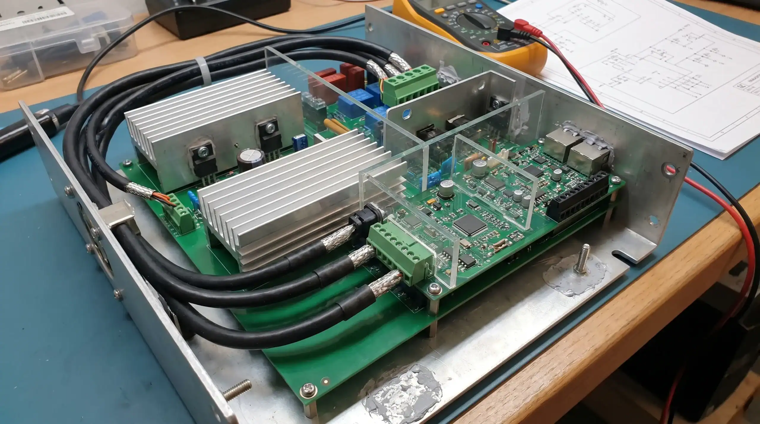
A schematic can be electrically correct while the PCB layout creates reliability problems. This is especially true in products that combine power electronics, analogue signals, wireless communication, high-speed digital interfaces or long external cables.
PCB layout choices influence EMC behaviour, signal integrity, heat distribution, insulation distances and manufacturability. Return current paths, loop areas, separation between noisy and sensitive circuits, connector placement and grounding all affect how the product behaves in real installations.
Common reliability risks include high-current paths routed too close to sensitive analogue circuits, insufficient creepage and clearance, poor thermal relief around power components, inadequate filtering at cable entries and ground structures that force noise through measurement or communication circuits.
EMC should be considered during architecture and layout, not only during certification testing. Pre-compliance measurements and design reviews can reduce the risk of late redesigns. For a deeper introduction to this topic, ProMicro’s article on what EMC means in electronic product design explains why electromagnetic compatibility should be part of the design process from the start.
Analogue and sensor interfaces need protection from the real world
Analogue electronics and sensor interfaces often define the quality of a product’s decisions. If a sensor signal is noisy, drifting or incorrectly conditioned, the embedded system may make the wrong control decision even though the software is functioning correctly.
Reliable analogue design considers the full signal chain. Sensor selection, excitation, filtering, impedance, shielding, ADC reference stability, calibration and connector strategy all matter. In industrial and maritime environments, cable length and external interference may have a major influence on measurement accuracy.
The same applies to printed electronics, current sensing, motor feedback, battery monitoring and other measurement functions. Accuracy in a controlled lab environment is not enough. The design must remain stable across temperature, ageing, electromagnetic disturbance and manufacturing tolerances.
A good analogue design approach also defines how the product detects implausible values. If a sensor becomes disconnected, saturated or noisy, the embedded system should not blindly trust the measurement. It should identify the fault and move to a controlled behaviour where possible.
Firmware choices affect hardware reliability
Embedded firmware is not separate from product reliability. It decides how the electronics start, recover, communicate, log faults and respond to abnormal conditions. A robust hardware design can still fail in the field if firmware assumes ideal behaviour.
Important firmware reliability choices include watchdog strategy, bootloader design, brownout handling, communication timeouts, memory protection, fail-safe states, diagnostic logging and update management. Firmware should also handle partially failed hardware, unavailable sensors, interrupted communication and power loss during critical operations.
This is where hardware and software co-design becomes important. The firmware team needs to understand the electrical behaviour of the system, and the hardware team needs to understand how software will use the electronics. For example, a diagnostic function may require current sensing, voltage monitoring or non-volatile memory. If those needs are not considered early, reliability features may be difficult or expensive to add later.
In complex products, embedded systems reduce risk by making product behaviour observable and controllable. ProMicro explores this broader relationship in its knowledge article on how embedded systems reduce risk in complex product development.
Component selection is about more than availability today
A component can be technically suitable and still create reliability or lifecycle risk. Engineers often evaluate components based on electrical specifications, package, cost and availability. Those factors are important, but for professional products the decision should also include derating, temperature grade, supplier maturity, qualification data, expected lifetime and second-source options.
Component lifecycle management has become a strategic issue for many OEMs. Products in industrial, defence, maritime or machine-building markets may need support for many years. If a critical IC, connector or display becomes unavailable shortly after launch, the product may require redesign, requalification or changes to production test.
Reliability-focused electronic design therefore considers the bill of materials as part of the product lifecycle. Selecting a part is not only a purchasing decision. It is an engineering decision that affects thermal margin, EMC behaviour, manufacturability, serviceability and long-term continuity.
Mechanical integration influences electrical behaviour
The enclosure is not only a container for the PCB. It is part of the electrical, thermal and EMC design. Mechanical decisions influence airflow, heat spreading, antenna performance, cable strain, ingress protection, connector accessibility and user handling.
For example, a compact enclosure may create thermal stress if heat-generating components are not connected to a suitable heat path. A metal enclosure may help with shielding, but only if grounding, seams, cable entries and apertures are designed correctly. A plastic enclosure may be suitable for many applications, but it may require additional EMC measures or careful antenna placement.
Connectors deserve particular attention. They are often exposed to mechanical stress, moisture, handling errors and contamination. Connector choice affects sealing, mating cycles, current rating, vibration resistance and serviceability. In many field failures, the root cause is not the integrated circuit or processor, but an interface between the product and its environment.
Design for manufacturing and testing prevents hidden production failures
A reliable prototype is not the same as a reliable production design. Prototype builds often depend on manual attention, flexible rework and expert knowledge. Volume manufacturing requires repeatable assembly, inspection, programming, calibration and end-of-line testing.
Design for manufacturing and design for test should be considered before the PCB is released. Test points, programming interfaces, calibration access, fixture strategy and traceability all influence production quality. If the product cannot be tested efficiently, defects may escape into the field or production costs may rise unexpectedly.
Manufacturing preparation also includes tolerances, assembly process limits, thermal profiles, coating or potting decisions, enclosure assembly and service instructions. A design that is difficult to assemble consistently will not become reliable simply because the prototype worked.
This is why end-to-end electronic design support can be valuable. It connects the engineering choices made in concept and prototype phases with the practical needs of production, qualification and long-term support.
Reliability continues after launch
Product reliability is not finished when the first production batch leaves the factory. Field feedback, service data, firmware updates, component changes and supplier notifications all affect the product lifecycle.
For connected products and professional equipment, launch readiness also includes clear documentation, support content and customer communication. That communication layer does not replace engineering reliability, but it helps users install, operate and maintain the product correctly. When the digital presence around a product needs specialist support, teams may involve external partners such as Sleek Web Designs while the engineering team remains focused on product integrity.
From an electronics perspective, lifecycle readiness means designing for controlled change. Firmware should be maintainable. Components should be monitored for availability. Production tests should remain documented and repeatable. Known field issues should feed back into future revisions.
How ProMicro approaches reliability in electronic design
ProMicro supports companies that need to develop reliable electronic products from idea generation to volume solutions. That support combines embedded system development, power electronics, analogue electronics, PCB design, system engineering, enclosure design, rapid prototyping, manufacturing preparation and lifecycle thinking.
The practical value is not only extra engineering capacity. It is the ability to look beyond the immediate assignment and identify hidden risks early. In complex products, those risks often sit between disciplines: a power stage that affects EMC, a firmware decision that requires hardware diagnostics, a sensor interface that depends on mechanical placement, or a PCB layout that influences certification readiness.
For OEMs, machine builders, high-tech companies and product development teams, this integrated view helps reduce costly iterations. It also supports better decisions around compliance, scalability, manufacturability and long-term product support.
A strong electronics design partner should challenge assumptions, clarify requirements, make trade-offs visible and keep the development path connected to real operating conditions. That is how electronic design choices become reliability choices.
Frequently asked questions
What is the most important electronic design choice for product reliability? The most important choice is usually the system architecture, because it determines how power, signals, software, protection and fault behaviour interact. Good architecture makes later design decisions more controlled and reduces the chance that one fault affects the whole product.
When should EMC be considered in the development process? EMC should be considered from the concept and architecture phase. Waiting until formal testing can expose problems too late, when PCB layout, enclosure design, cabling and filtering choices are already difficult to change.
Why do prototypes often work in the lab but fail in real use? Lab prototypes are often tested with clean power, controlled temperatures, short cables and expert handling. Real products face voltage disturbances, heat, vibration, moisture, electromagnetic interference, user errors and production variation. Reliable design accounts for those conditions early.
Can an external electronics design partner work alongside an internal engineering team? Yes. Many companies use an external partner to add specialist expertise or capacity while keeping ownership of the product vision. This works best when requirements, responsibilities, IP expectations and technical decision points are clearly defined.
Does designing for reliability guarantee certification approval? No design partner can guarantee certification results in advance. However, designing with EMC, RED, CE, safety and manufacturing requirements in mind from the start can reduce risk, improve test readiness and limit the chance of late-stage redesign.
Build reliability into your next electronic product
If you are developing a product where electronics, embedded software, power behaviour, sensors, connectivity and manufacturing readiness all need to work together, reliability should be part of the design strategy from day one. ProMicro helps technical teams turn complex product ideas into robust, scalable and production-ready electronic solutions. Contact ProMicro to discuss how early design choices can reduce risk in your next development project.
