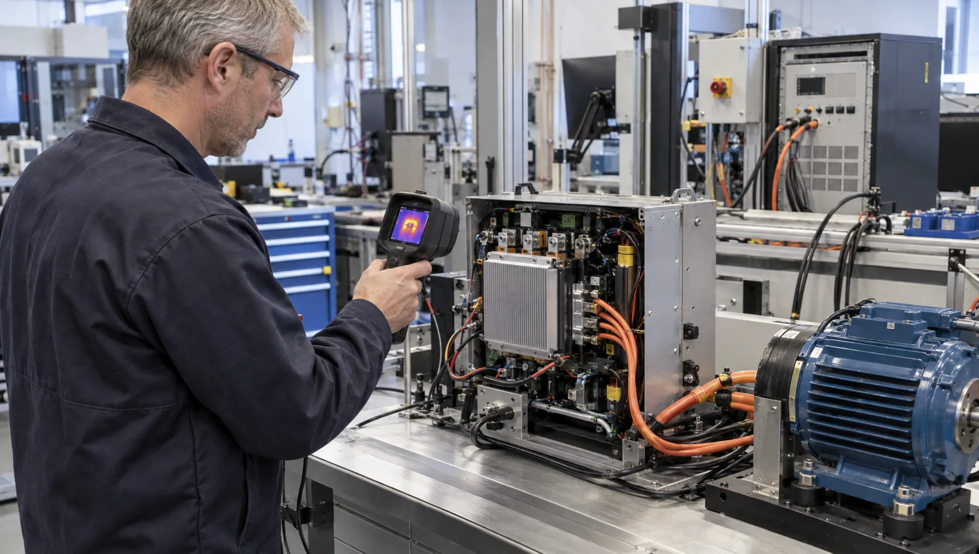
Reliable electrical monitoring in an industrial motor drive must do more than display current and voltage. It must support stable control, detect damaging conditions and provide diagnostic evidence without being misled by PWM switching noise. A measurement that looks accurate on a laboratory bench may become unreliable when the drive operates with long motor cables, regenerative loads or a hot power stage.
The design therefore starts with the decisions each measurement must support. Fast semiconductor protection, current-loop feedback and maintenance diagnostics need different bandwidths, accuracy levels and failure responses. Treating them as one measurement task creates avoidable compromises.
This guide focuses on monitoring inside an inverter-based motor drive, rather than facility-level energy metering. It connects sensor selection, analogue conditioning, embedded firmware and verification so that development teams can define a system that remains useful from prototype testing through volume production.
What must electrical monitoring detect?
Begin with a requirements matrix linking each monitored quantity to an action. “Measure motor current” is incomplete unless the specification also defines the operating range, required response time and behaviour when the measurement becomes invalid.
| Quantity | Typical purpose | Important design constraint |
|---|---|---|
| Phase current | Torque control, current limiting and overload detection | PWM-dependent sampling windows and bidirectional range |
| DC-link voltage | Undervoltage detection and regenerative overvoltage management | Transient headroom and divider behaviour |
| DC-link current | Input power estimation and fault diagnostics | Sensor location relative to the DC-link capacitor |
| Power-stage temperature | Thermal derating and overheating detection | Sensor placement and thermal lag |
| Gate-driver fault status | Detection of switching-stage faults | Independent response path and fault latching |
Separate normal operation, temporary overload and fault conditions. Include acceleration, braking, blocked-rotor operation and loss of a sensor supply where these are relevant to the application.
A useful requirement states both a performance target and its conditions: maximum current error across the specified temperature range, for example, rather than accuracy at room temperature alone. Also define which measurements remain trustworthy during startup, shutdown and fault recovery.
Choose current sensing around the inverter topology
The location of a sensor determines what electrical monitoring can observe, not just how much the circuit costs. Phase-current sensors, low-side shunts and a single DC-link shunt provide different information and sampling opportunities.
Three phase-current channels offer direct measurements and a useful consistency check in a three-wire motor circuit. Two measured currents can support reconstruction of the third under suitable conditions. Single-shunt reconstruction requires a deliberate modulation and sampling strategy because some switching states provide insufficient measurement windows.
Match the sensor to the waveform and environment
| Sensing approach | Strength | Main limitation to evaluate |
|---|---|---|
| Shunt resistor with amplifier | Direct measurement of DC and AC current | Dissipation, offset errors and common-mode requirements |
| Hall-effect sensor | DC and AC sensing with an isolated measurement path | Offset drift, bandwidth and magnetic interference |
| Current transformer | AC measurement without a resistive insertion loss | Cannot measure steady DC and may saturate |
| Rogowski coil | Measurement of rapidly changing current | Requires integration and cannot measure steady DC |
Isolation capability and safety ratings depend on the complete implementation, not the sensor category alone.
For a shunt, calculate losses before committing to the PCB. An illustrative 200 µΩ shunt carrying 100 A RMS dissipates 2 W, using P = I²R. At 100 A instantaneous current, its signal is only 20 mV. That combination makes thermal design, Kelvin connections and amplifier offset consequential.
Check pulse capability separately from continuous dissipation. A shunt that survives a short peak may still drift excessively at sustained load.
Measure the DC link with the right electrical boundary
Voltage and current measurements only become meaningful when their locations are documented. For electrical monitoring, the current entering the DC-link capacitor is not interchangeable with the current flowing from that capacitor into the inverter bridge.
A sensor upstream of the capacitor observes a different waveform from a bridge-input sensor. During regeneration, current can reverse, so the measurement chain must support the intended polarity range without clipping.
For voltage sensing, size the divider and conditioning circuit for credible maximum voltage, not nominal operation alone. Consider resistor working-voltage ratings, power dissipation, tolerances, creepage and clearance. Multiple series resistors may be needed to distribute voltage stress, depending on component ratings and insulation requirements.
Include an analogue response to transients. Input clamps must not compromise measurement accuracy or leave the amplifier recovering slowly after overload.
DC input power is not motor shaft power. Multiplying synchronised DC-link voltage and current can support electrical power estimation at that measurement boundary. Shaft power additionally requires mechanical information or a justified loss model. Motor-terminal power measurement is more demanding because PWM waveforms require suitable bandwidth, voltage references and closely aligned sampling.
Synchronise acquisition with PWM switching
An ADC conversion taken near a switching edge may capture ringing or amplifier recovery rather than useful motor current. Reliable electrical monitoring therefore depends on coordinating PWM generation, analogue settling and ADC triggering.
For an illustrative switching frequency of 20 kHz, one PWM period lasts 50 µs. That does not mean every point within the period is available for measurement. Dead time, switching transitions, blanking intervals and minimum pulse widths reduce the valid window.
Trigger conversions from the timer that generates the PWM where the controller architecture supports it. Define valid sampling positions for each modulation state and verify them at minimum and maximum duty cycles. For shunt reconstruction, explicitly handle states where the required window disappears.
Filtering also needs a defined purpose. Analogue filtering limits unwanted bandwidth before conversion, while digital filtering can smooth acquired data. Digital filtering cannot undo aliasing that has already occurred at the ADC input.
Keep fast control measurements separate from slower trend values. A heavily filtered RMS-current estimate may suit overload supervision but introduce unacceptable delay into a current-control loop.
Timestamp measurements and status flags consistently. If voltage and current samples refer to different switching conditions, calculated power can be misleading even when each channel is individually accurate. Verify acquisition timing with oscilloscope measurements, rather than relying only on firmware configuration.
Build an accuracy and latency budget
An electrical monitoring specification should allocate error across the complete signal chain: sensor, amplifier, reference, ADC, layout and processing. ADC resolution alone does not establish system accuracy.
For example, a 12-bit converter mapped across a ±200 A range has an ideal code width of approximately 0.098 A. That figure says nothing about sensor offset, reference drift or switching interference. With a 200 µΩ shunt, an input-referred offset of 0.2 mV corresponds to a 1 A current error before other contributions are included.
Build the budget across the operating temperature range. Include gain error, offset drift, resistor temperature coefficients and reference stability. Treat random noise differently from bounded systematic errors rather than combining every contribution using the same method.
ProMicro’s guide to analogue electronics design for accurate industrial products provides further context on conditioning and error budgets. In a drive, these principles must also account for the inverter’s switching environment.
Latency deserves a separate budget. Add sensor response, amplifier settling, filter delay, acquisition time and processing delay. A channel can meet its accuracy target yet react too slowly for its assigned task.
For isolated channels, check common-mode transient immunity alongside bandwidth and insulation ratings. Manufacturer documentation such as the TI AMC1301 data sheet specifies these as distinct characteristics. Adequate isolation voltage does not by itself establish measurement integrity during fast switching edges.
Keep rapid protection independent of telemetry
A firmware task that logs current every millisecond is not a semiconductor protection mechanism. The permissible fault-response time must come from the power devices, gate drivers and fault-energy analysis.
Where the architecture requires it, use hardware overcurrent detection, gate-driver desaturation detection or another suitably fast protection path. A hardware trip can inhibit switching while firmware records the event and manages recovery. The exact shutdown sequence must account for switching-device behaviour and stored energy.
Electrical monitoring should report these events without becoming the only defence against them. Review whether a failed ADC, stalled processor or broken sensor connection can prevent the necessary protective action.
Distinguish an equipment-protection trip from a claimed functional safety function. Safe torque off, for example, is not automatically provided by measuring current and stopping PWM in ordinary firmware.
IEC 61800-5-1 addresses electrical, thermal and energy safety requirements for adjustable-speed power drive systems. IEC 61800-5-2 addresses functional safety aspects where applicable. Their relevance and the required implementation depend on the product boundary and intended claims.
Define fault latching, reset permissions and restart behaviour early. An automatic restart after a transient may be acceptable in one machine and hazardous in another. Coordinate the drive’s behaviour with the machine-level safety concept rather than deciding it solely within the electronics team.
Turn measurements into credible diagnostics
Diagnostic value comes from combining measurements with operating context. A high current reading during acceleration means something different from the same reading at constant speed with a lightly loaded motor.
Useful electrical monitoring records should therefore include speed demand, operating state, DC-link voltage, temperature and relevant fault flags alongside current. Mark reconstructed or invalid samples so that downstream software does not treat them as direct, trustworthy measurements.
Use persistence timers and hysteresis for conditions that do not require immediate shutdown. These can prevent alarm chatter, but their delays must remain compatible with the thermal or electrical risk being managed.
Distinguish observation from diagnosis. Rising current might indicate mechanical loading, a control problem or a measurement fault. Increased DC-link ripple might reflect load changes, supply conditions or capacitor degradation. Neither measurement alone proves a specific failure mechanism.
A pre-fault and post-fault buffer can help engineers investigate an event, provided its sample rate and duration match the phenomenon of interest. Separate this high-rate capture from long-term trend logging, and avoid writing continuously to non-volatile memory without considering endurance.
Finally, define what leaves the drive through its communications interface. Units, scaling, timestamps, validity flags and firmware-version information make field records interpretable. Without these, a numeric register may be available but difficult to use reliably across product revisions.
Validate under switching and installation stress
Bench calibration with the inverter disabled is only one part of validation. Electrical monitoring must also be tested while the drive switches, changes load and experiences the disturbances expected in its installation.
Use a verification matrix that crosses operating conditions with measurement and fault-response requirements. Include representative motor types, cable lengths, load profiles and enclosure configurations. Record the PWM strategy and firmware version used for each test.
The most revealing tests often include:
- Maximum intended switching slew rate and representative motor-cable configurations.
- Minimum and maximum duty cycles, including current-reconstruction limits.
- High-load operation at the specified temperature limits.
- Acceleration, regeneration and DC-link voltage excursions.
- Sensor faults, acquisition failures and controlled protection tests using an appropriate safety setup.
Evaluate measurement corruption as well as resets or permanent damage. A disturbance that shifts a current reading without crashing the controller can still affect torque control or protection thresholds.
Cable-related disturbances deserve particular attention. ProMicro’s explanation of how EMC engineering controls cable coupling describes mechanisms that can influence the drive’s sensing and interface circuits.
IEC 61800-3 provides EMC requirements and test methods for power drive systems. Select applicable requirements with the intended environment and installation boundary in mind. A successful drive test does not automatically establish compliance of the complete machine or every installation.
Design calibration and test for production
A monitoring channel is not production-ready until its performance can be checked repeatably. Decide during development which parameters require calibration and which can be controlled through component selection and design margin.
For electrical monitoring, production tests should distinguish genuine calibration errors from assembly defects, incorrect component values and failed isolation or signal paths. Calibrating around a hardware defect can hide a problem rather than solve it.
Provide access for test equipment without compromising high-current routing, insulation distances or EMC performance. Define safe test conditions and fixture limitations, especially where powered measurements involve hazardous voltages.
Store calibration data with integrity checks and a defined fallback policy. Establish whether recalibration is required after replacing a current sensor, power board or controller. Maintain traceability between hardware revision, firmware revision and calibration format.
Component substitutions also need measurement-focused review. A replacement amplifier with similar gain and bandwidth may have different overload recovery, common-mode behaviour or drift. Requalification should reflect the affected requirements, not merely confirm that the drive still runs.
The practical development output should be a linked set of requirements, schematics, timing definitions, calibration procedures and verification evidence. That gives manufacturing and lifecycle teams a usable basis for maintaining the product.
Frequently asked questions
Can one current sensor support control, protection and diagnostics? Sometimes, but electrical monitoring must account for conflicting bandwidth, latency and fault-tolerance needs. A shared sensor can feed separate processing paths, while rapid protection may still require an independent comparator or gate-driver mechanism. Review common failure modes before accepting a shared architecture.
Is a higher-resolution ADC always better? No. Additional resolution is useful only if noise, offset, reference stability and timing allow it to be used. Better sensing layout or synchronised acquisition may improve performance more than increasing the nominal bit count.
Should every motor drive use isolated current sensing? No. The answer depends on sensor location, voltage domain, controller architecture and insulation requirements. Low-side shunts can suit some designs, while other architectures need isolated phase-current measurements. Assess the complete insulation and signal chain.
Can monitoring data predict motor or drive failures? It can support condition assessment, but predictive claims need validation against representative operating and failure data. Current, voltage and temperature trends are evidence to interpret, not automatic proof of a failing bearing, winding or capacitor.
Review the monitoring architecture before PCB commitment
Before layout begins, agree on the measurement boundaries, error budgets, sampling windows and protection responsibilities. Then confirm how those decisions will be verified and maintained in production.
ProMicro combines power electronics, analogue design, embedded systems and firmware with PCB design, prototyping and manufacturing support. For a motor-drive project, that integrated approach helps teams address sensing, control, EMC and qualification risks together rather than discovering incompatible assumptions after the first prototype.
A useful starting point is a technical review of the operating envelope, monitoring requirements and planned fault responses, especially where internal teams need additional specialist capacity.