
An assembled circuit board can look deceptively complete. Components are soldered, connectors are in place, firmware may even boot, and the first functional tests may pass. For an engineering team under launch pressure, that can feel like the final stretch.
In reality, the first working printed circuit board assembly (PCBA) is not yet a production-ready product. It is a technical proof point. To become ready for manufacturing, certification and long-term field use, it must be inspected, measured, tested, documented and improved in a controlled way.
For OEMs, machine builders, robotics companies, defence suppliers, maritime technology providers and high-tech manufacturers, this distinction matters. A board that works on the bench may still fail under vibration, thermal stress, electrical noise, poor installation conditions or component variation. Production readiness is the process of reducing those risks before they become expensive production or field problems.
Production-ready is an evidence state, not a build stage
A production-ready assembled circuit board is not simply a board that has passed a quick functional test. It is a board supported by evidence that it can be built repeatedly, tested objectively and used reliably within its intended operating environment.
That evidence usually covers several areas:
- The electronics meet the defined functional requirements.
- The assembly process is repeatable and controlled.
- Critical parameters can be tested during production.
- EMC, safety and thermal risks have been considered early enough.
- The bill of materials is realistic for procurement and lifecycle support.
- Firmware, calibration data and production documentation are under version control.
- The board can be integrated into the enclosure, machine or product without creating new risks.
This is why the journey from prototype to production is not a single handover to a manufacturer. It is an engineering process. For a broader view of the assembly journey, ProMicro also explains how printed circuit board assembly moves from prototype to volume, including reliability, manufacturability and testability considerations.
Start by validating requirements against real use
Before the first board is powered, the team should revisit the product requirements. This is where many later production problems begin. The schematic may match the visible specification, but the real application often adds hidden requirements.
A motor drive in a machine may face switching noise, long cable runs and temperature peaks. A maritime product may need to tolerate humidity, salt exposure and supply disturbances. A connected device may need to behave predictably when wireless reception is poor. A defence or professional mobility application may require higher resilience against vibration, shock or maintenance errors.
The objective is to translate those conditions into measurable acceptance criteria. Instead of saying “the board must be robust”, define what voltage range, temperature range, load conditions, communication behaviour, enclosure constraints and diagnostic behaviour will be verified. Without this step, test results remain subjective.
Good production readiness starts with clear engineering intent. The assembled board is then evaluated against the product’s real operating context, not only against a schematic checklist.
Inspect assembly quality before electrical bring-up
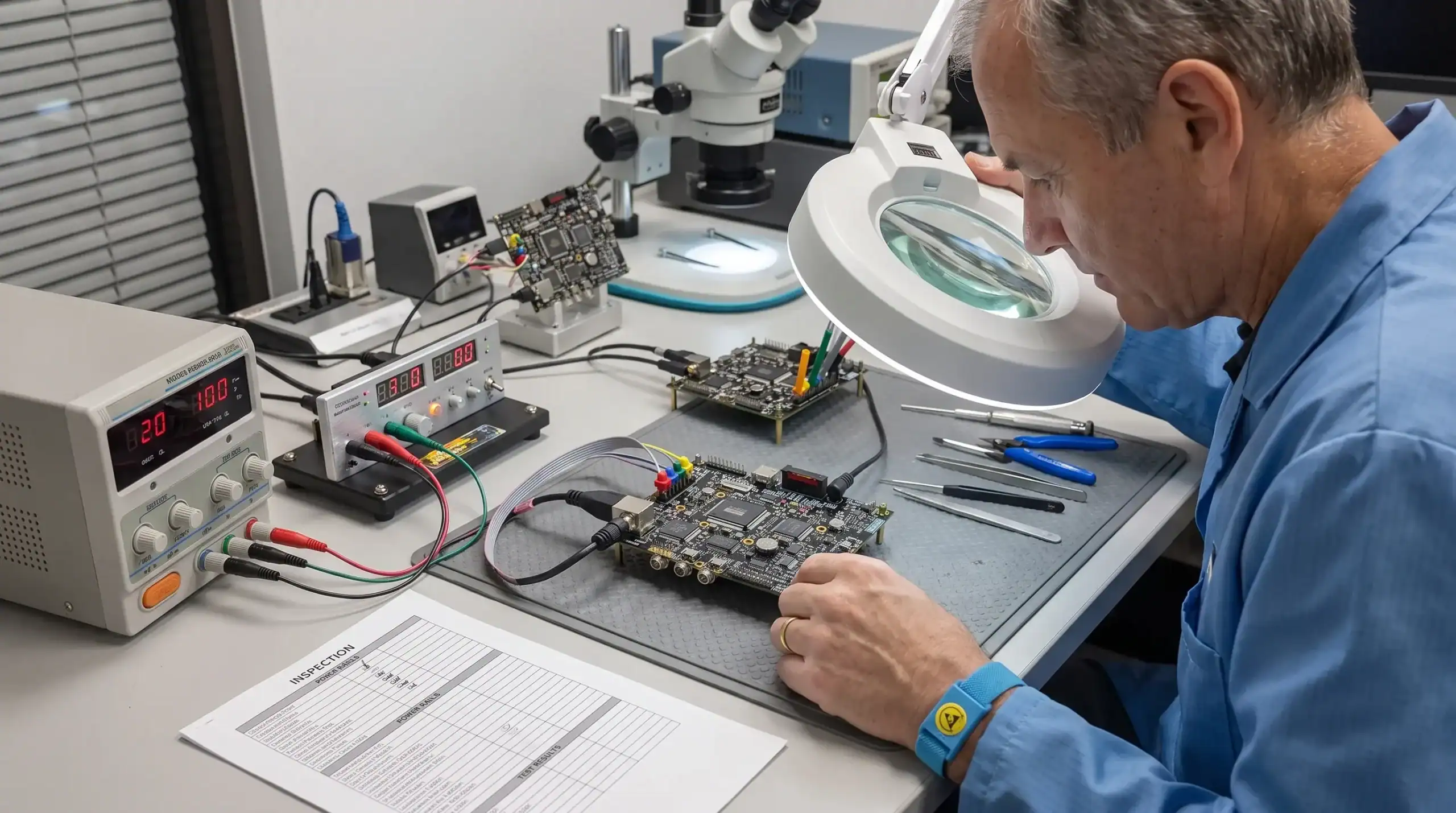
The first production-readiness gate is physical inspection. Electrical debugging on a poorly assembled board wastes time and can damage components. Inspection also helps separate design issues from assembly process issues.
Typical checks include component placement, polarity, solder joint quality, connector alignment, cleanliness, mechanical clearance and visible damage. For fine-pitch packages, BGAs or dense assemblies, automated optical inspection or X-ray inspection may be needed. Acceptance criteria are often based on recognised electronics assembly standards such as IPC-A-610, combined with product-specific requirements.
This inspection is not only about finding defects. It also reveals whether the board is easy to assemble. Ambiguous polarity markings, crowded components, inaccessible connectors or inconsistent reference designators are early warning signs. If they are ignored, they can reduce production yield later.
Bring-up should be controlled and instrumented
The first power-on is a risk moment. A structured bring-up procedure reduces the chance of damaging boards and gives the engineering team useful baseline data.
A controlled bring-up normally starts with current-limited supplies, measurement of power rails and confirmation of expected start-up sequencing. Engineers verify clock signals, reset behaviour, bootloader access, programming interfaces, communication buses and thermal behaviour under light load. Protection circuits should also be checked carefully, especially where external power, motors, batteries, actuators or long cables are involved.
The goal is not only to make the board run. The goal is to understand whether its behaviour is repeatable and explainable. Current consumption, rail stability, regulator temperature, analogue noise levels and boot timing should be recorded. These values become reference points for later prototypes, pilot builds and production tests.
If deviations appear, they should be captured in a structured issue list. Lab observations, firmware versions, measurement conditions and board serial numbers all matter. Without traceability, the same issue can reappear during pilot production with no clear root cause.
Functional testing must include boundaries, not only nominal behaviour
A board that passes nominal functional tests may still fail in the field. Production readiness requires testing at the boundaries of expected operation.
For an embedded control board, that may include low and high supply voltage, rapid power cycling, sensor disconnection, communication loss, firmware recovery, actuator overload and fault logging. For analogue electronics, it may include offset drift, noise sensitivity, calibration stability and tolerance stack-up. For power electronics, it may include load transients, thermal rise, switching behaviour and protection response.
The test strategy should also distinguish between engineering validation and production test. Engineering validation explores whether the design is robust. Production test confirms that each manufactured unit meets defined acceptance criteria within a practical test time.
| Area | Prototype evidence | Production-ready evidence |
|---|---|---|
| Function | Core features work on one or more sample boards | Functions are verified across defined operating conditions |
| Assembly | The board can be assembled once | Assembly is repeatable with acceptable yield and clear instructions |
| Testability | Engineers can probe signals manually | Critical functions can be tested using fixtures, scripts or defined procedures |
| Firmware | Firmware runs on the board | Firmware versioning, programming and recovery are controlled |
| Compliance risk | No obvious issue in the lab | EMC, safety, thermal and radio risks are reviewed before certification testing |
| Supply chain | Components are available for prototypes | Approved parts, alternates and lifecycle risks are documented |
| Documentation | Design files exist | Manufacturing, inspection, programming and test data are controlled |
Design for manufacturing and test closes the gap
Many boards reach a working prototype stage with small compromises that seem harmless. In production, those compromises can create cost, delay or inconsistent quality.
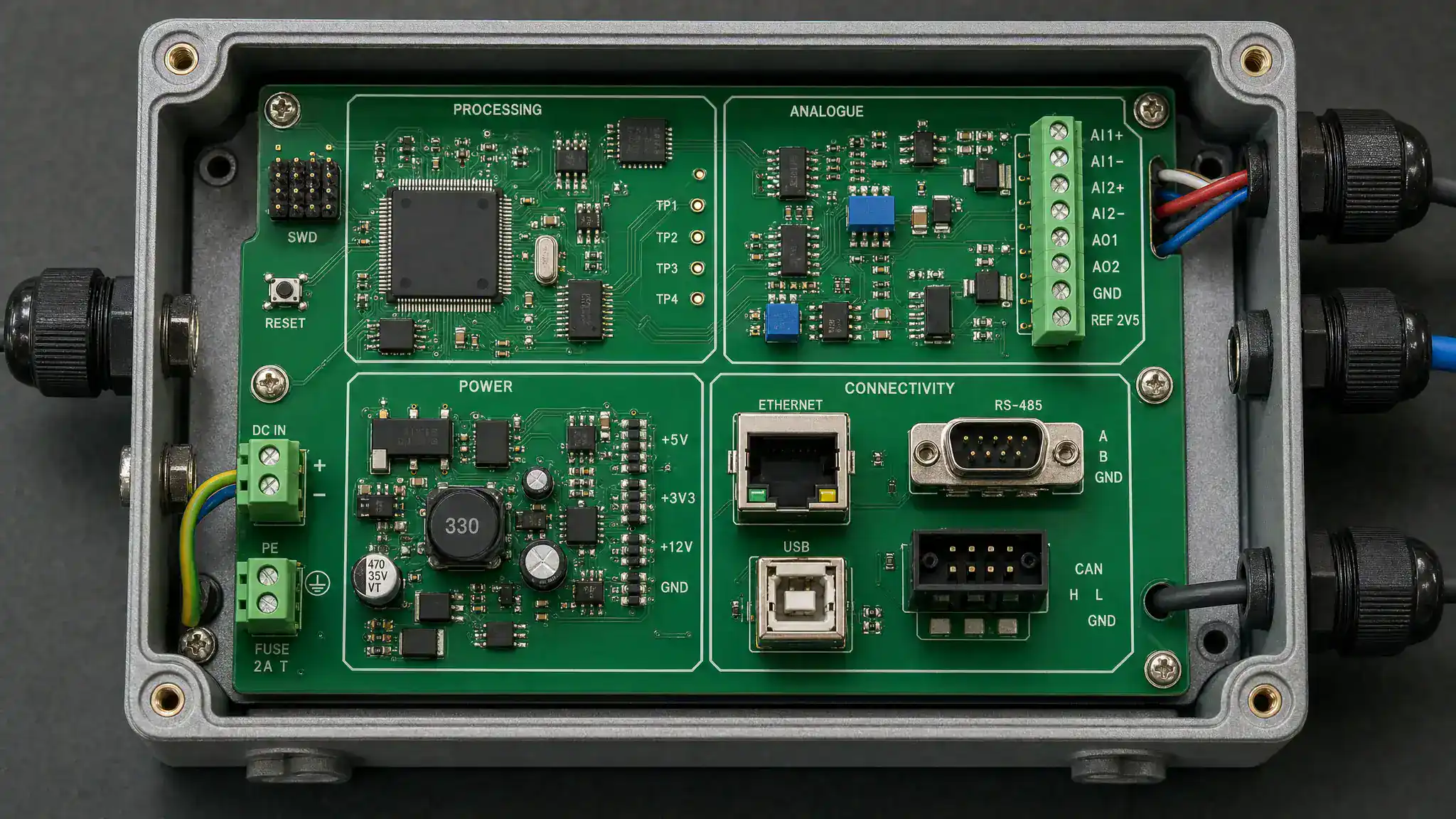
Design for manufacturing reviews look at factors such as component spacing, solderability, stencil requirements, thermal mass, connector access, panelisation, fiducials, depanelisation stress and assembly orientation. Design for test reviews focus on test pads, programming access, calibration points, serialisation, fixture access and safe ways to stimulate inputs or loads.
This is also where collaboration between the electronics designer, embedded software engineer, mechanical engineer and assembly partner becomes critical. For example, a test pad may be electrically useful but inaccessible once the board is placed in an enclosure. A connector may be acceptable on the PCB but difficult to reach during final machine assembly. A high-current trace may pass initial tests but heat the enclosure locally under continuous load.
The earlier these details are reviewed, the less expensive they are to correct. If your team is still before the first build, ProMicro’s guide on preparing a PCB design for prototyping and volume build covers many of the design decisions that influence the later production process.
EMC, safety and environmental risks need early engineering attention
Certification should not be treated as a final administrative step. EMC, RED, CE and safety-related requirements influence architecture, layout, grounding, shielding, filtering, firmware behaviour, enclosure design and cable strategy.
An assembled circuit board should therefore be evaluated with compliance in mind before the formal test campaign. Pre-compliance measurements, near-field probing, conducted emission checks, immunity investigations and ESD testing can reveal weaknesses while the design can still be adjusted.
This is especially important for products that include wireless communication, motor drives, switching power supplies, long sensor cables or external interfaces. These features often create interactions that are not visible during basic bench testing. A device may function correctly in isolation but disturb other equipment, or it may become unstable when exposed to external interference.
Thermal and environmental testing also deserves attention. Temperature rise, condensation risk, vibration, connector retention, corrosion exposure and enclosure airflow can all influence board reliability. The board, firmware and enclosure should be considered as one system rather than separate design tasks.
For teams working with connected products, power electronics or safety-sensitive environments, ProMicro’s article on embedded design decisions that affect EMC, safety and lifecycle gives further context on why these risks should be addressed early.
The manufacturing data pack must be complete and controlled
A board cannot be production-ready if the manufacturer has to interpret missing information. The manufacturing data pack is the bridge between engineering intent and repeatable production.
It normally includes PCB fabrication data, assembly data, bill of materials, approved vendor information, pick-and-place files, assembly drawings, firmware files, programming instructions, calibration procedures, test instructions, inspection criteria and packaging requirements. For professional products, traceability may also require serial numbers, batch records, firmware version records and component lot information.
The key point is control. If a resistor value changes, firmware is updated or an alternative component is approved, the change must be documented. Otherwise, different product batches may behave differently, even though they appear to be the same product.
A controlled data pack also supports long-term maintainability. When a product returns from the field, the team must be able to identify the exact hardware revision, firmware version and production history. This is essential for root-cause analysis, warranty handling and future product improvements.
Pilot production proves repeatability
Pilot production is where the design meets real manufacturing variation. It is usually the first opportunity to observe how the board behaves when built in a controlled batch rather than as a small engineering sample.
During a pilot build, teams should monitor yield, rework reasons, test failures, operator questions, programming time, calibration time and any ambiguity in work instructions. Even small issues matter. A connector that requires manual correction, a label that is easy to place incorrectly or a test fixture that gives inconsistent readings can become significant at higher volume.
Pilot production should not be viewed as a formality. It is a feedback loop. The findings may lead to PCB layout changes, component changes, firmware updates, fixture improvements or clearer assembly documentation. Each improvement reduces risk before the product enters a more committed manufacturing phase.
Lifecycle planning is part of production readiness
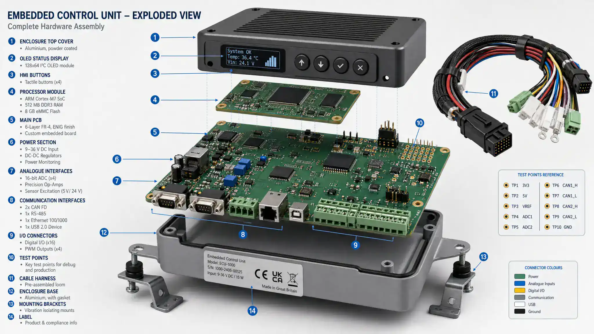
Production readiness also extends beyond the first manufacturing run. Professional products often need to remain available, serviceable and compliant for years. That requires lifecycle thinking.
Component availability is a major factor. Parts used in prototypes may become constrained, discontinued or unsuitable for future volumes. Approved alternates should be evaluated where appropriate, especially for critical components such as microcontrollers, power semiconductors, connectors, sensors and wireless modules.
Firmware lifecycle is equally important. The team should define how firmware is programmed, updated, secured, identified and recovered. If a product includes connectivity, the update strategy, diagnostic behaviour and compatibility with future versions should be considered before deployment.
The production environment itself can also influence readiness. Test rigs, burn-in equipment, charging systems and climate chambers may increase energy demand or require changes to facility planning. For companies in the Arnhem-Nijmegen region that need to align production expansion with energy constraints, subsidies or grid capacity, independent advice on energy saving and net congestion can help identify practical next steps.
Warning signs that a board is not yet production-ready
Several signals indicate that a working board still needs engineering work before it can safely move to volume production:
- Test results depend on one engineer’s manual procedure.
- The firmware version on tested boards is unclear.
- EMC or safety considerations are postponed until after final layout.
- The manufacturer has to make assumptions about assembly details.
- Critical components have no approved alternatives or lifecycle review.
- The board works in the lab but has not been tested under realistic load, temperature or disturbance conditions.
- Rework is accepted as normal instead of being treated as a process or design issue.
These issues do not mean the project has failed. They mean the board is still in an engineering maturation phase. Recognising that early is far less costly than discovering it during certification, production ramp-up or customer deployment.
How a technical partner adds value
For many OEMs and technical companies, the challenge is not a lack of engineering capability. It is limited capacity, specialist knowledge or time to manage every risk across electronics, embedded software, power behaviour, analogue performance, PCB layout, mechanical integration, compliance preparation and manufacturing support.
A strong electronics development partner helps turn the assembled board into a controlled product. That means asking questions beyond the immediate assignment, identifying hidden requirements, reviewing manufacturability, defining test strategies, supporting prototyping and preparing the product for volume manufacturing.
The value lies in integration. A production-ready board is not created by PCB layout alone, firmware alone or assembly alone. It is created by aligning system architecture, electronic design, embedded software, enclosure constraints, compliance considerations and manufacturing reality.
Frequently asked questions
What is an assembled circuit board? An assembled circuit board is a printed circuit board fitted with electronic components such as ICs, resistors, capacitors, connectors and modules. It is often called a printed circuit board assembly or PCBA.
When is an assembled circuit board production-ready? It is production-ready when its function, manufacturability, testability, documentation, compliance risks and lifecycle considerations have been verified well enough to support repeatable manufacturing and reliable field use.
Is a working prototype enough to start volume production? Usually not. A working prototype proves that the concept can function, but volume production requires controlled assembly data, test procedures, supply chain review, pilot production feedback and evidence that the design works under realistic conditions.
Should EMC testing happen before or after assembly? EMC thinking should start during architecture and PCB design, but assembled boards are needed for practical pre-compliance and validation measurements. Waiting until final certification testing increases the risk of late redesign.
What documents are needed before production? Typical documents include fabrication files, assembly files, bill of materials, approved vendor lists, assembly drawings, firmware files, programming instructions, test procedures, inspection criteria and revision control records.
From working board to reliable product
Turning an assembled circuit board into a production-ready product is a structured engineering process. It requires inspection, controlled bring-up, functional validation, manufacturability review, compliance-aware design, pilot production learning and lifecycle planning.
For companies developing complex electronics, embedded systems, power electronics or connected products, this process reduces technical risk before it reaches the customer. ProMicro supports organisations that need to move from first idea and prototype to robust, scalable and production-ready electronics with the right balance of hardware, software, testing and manufacturing preparation.
